IBM 4840-544 Service Guide - Page 53
Troubleshooting
 |
View all IBM 4840-544 manuals
Add to My Manuals
Save this manual to your list of manuals |
Page 53 highlights
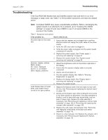
August 3, 2006 Troubleshooting Troubleshooting If the SurePOS 500 Models 5x3 and 544/564 system fails and there is no error message or beep code, see Table 7 to find problem symptoms and take the related action. Note: Corrupted CMOS may cause unpredictable problems. Before exchanging the system board in an attempt to fix a problem, go to "Clearing the CMOS settings" on page 23 and reset CMOS to see if corrupted CMOS is the source of the trouble. Table 7. Symptoms and actions If the problem is... Here's what to do. No power light on the tower unit. 1. Ensure that the system unit is plugged into a working electrical outlet and replug the power cable at the power supply. 2. Verify the LED card cable is plugged in. 3. Verify the power cable is plugged into the system board connectors P1 and P2. 4. Replace the power supply. See "Power supply - removing and replacing" on page 57. 5. Replace the system board. See "System board - removing and replacing" on page 65. Operator display exhibits: Blank screen No cursor displayed Screen is unreadable Other display problems. 1. Adjust the brightness control at the bottom right side of the display. 2. Ensure that the operator display cable is securely connected. 3. Switch unit off and back on. | 4. Run the operator display test. Refer to "Running | Diagnostics" on page 30.. 5. Replace the display tablet. See "Display tablet - removing and replacing" on page 48. 6. Replace the system board. Cash drawer does not open when cash drawer key is turned to the open position. 1. Replace the keylock insert if the lock does not turn with the key. See "Removing and replacing the keylock insert" on page 116. 2. Gently pull the drawer open while holding the key turned to the open position to determine if the slide assembly is binding. Look for items that may cause binds, such as pens or paper clips. Replace the slide assembly if necessary. See "Removing and replacing a full-size slide assembly" on page 106 or "Removing and replacing the compact slide assembly" on page 109. 3. Replace the cam, pawl, and spring kit. See "Removing and replacing components of the latch and sensor assembly" on page 115. 4. Check for a bent actuator rod. Replace the actuator rod if necessary. See "Removing and replacing the keylock assembly" on page 113. Chapter 3. Resolving problems 27
-
 1
1 -
2
-
3
-
4
-
5
-
6
-
7
-
8
-
9
-
10
-
11
-
12
-
13
-
14
-
15
-
16
-
17
-
18
-
19
-
20
-
21
-
22
-
23
-
24
-
25
-
26
-
27
-
28
-
29
-
30
-
31
-
32
-
33
-
34
-
35
-
36
-
37
-
38
-
39
-
40
-
41
-
42
-
43
-
44
-
45
-
46
-
47
-
 48
48 -
 49
49 -
 50
50 -
 51
51 -
 52
52 -
 53
53 -
 54
54 -
 55
55 -
 56
56 -
 57
57 -
 58
58 -
59
-
60
-
61
-
62
-
63
-
64
-
65
-
66
-
67
-
68
-
69
-
70
-
71
-
72
-
73
-
74
-
75
-
76
-
77
-
78
-
79
-
80
-
81
-
82
-
83
-
84
-
85
-
86
-
87
-
88
-
89
-
90
-
91
-
92
-
93
-
94
-
95
-
96
-
97
-
98
-
99
-
100
-
101
-
102
-
103
-
104
-
105
-
106
-
107
-
108
-
109
-
110
-
111
-
112
-
113
-
114
-
115
-
116
-
117
-
118
-
119
-
120
-
121
-
122
-
123
-
124
-
125
-
126
-
127
-
128
-
129
-
130
-
131
-
132
-
133
-
134
-
135
-
136
-
137
-
138
-
139
-
140
-
141
-
142
-
143
-
144
-
145
-
146
-
147
-
148
-
149
-
150
-
151
-
152
-
153
-
154
-
155
-
156
-
157
-
158
-
159
-
160
-
161
-
162
-
163
-
164
-
165
-
166
-
167
-
168
-
169
-
170
-
171
-
172
-
173
-
174
-
175
-
176
-
177
-
178
-
179
-
180
-
181
-
182
-
183
-
184
-
185
-
186
-
187
-
188
-
189
-
190
-
191
-
192
-
193
-
194
-
195
-
196
-
197
-
198
-
199
-
200
-
201
-
202
-
203
-
204
-
205
-
206
-
207
-
208
-
209
-
210
-
211
-
212
-
213
-
214
-
215
-
216
-
217
-
218
-
219
-
220
-
221
-
222
-
223
-
224
-
225
-
226
-
227
-
228
-
229
-
230
-
231
-
232
-
233
-
234
-
235
-
236
-
237
-
238
-
239
-
240
-
241
-
242
-
243
-
244
-
245
-
246
-
247
-
248
-
249
-
250
-
251
-
252
-
253
-
254
-
255
-
256
-
257
-
258
 |
 |
