IBM 4840-544 Service Guide - Page 112
underneath
 |
View all IBM 4840-544 manuals
Add to My Manuals
Save this manual to your list of manuals |
Page 112 highlights
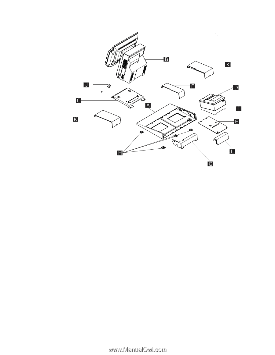
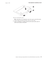
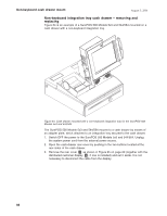
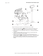
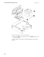
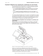
Non-keyboard countertop mount August 3, 2006 Figure 62. Countertop non-keyboard integration tray b. Remove the rear cover. See "Rear cover - removing and replacing" on page 38. c. Unplug the peripheral cables from the side and rear connector panels. d. Remove the thumbscrews (2) securing the system adapter plate C to the integration tray I , slide the system and adapter plate to the rear as a unit to free the plate from the mounting tabs, and lift off the system. e. Remove the system from the adapter plate (2 screws). To replace a system on a countertop or integration tray, reverse this procedure. Note: Secure the cables with tie-warps if desired. Cut the end of the tie-wraps flush so there are no jagged edges sticking out. 4. The installation of the filler panels is done after all the cables have been routed to your system. To install the integration tray filler panels, see Figure 63 on page 87. Note that filler panel A locks filler panels B onto the tray. The installation of the filler panels is done after all the cables have been routed to your system. a. Install the outer ends of the filler panels B onto the integration tray. Notice that the printer filler panel, shown on the right, is narrower than the system filler panel. Also, the system filler panel has a slot underneath to allow cables to be routed out the back. b. After installing the outer ends of filler panels B into the integration tray, use the narrow filler panel A to lock the filler panels together between the system and the printer. 86
-
 1
1 -
2
-
3
-
4
-
5
-
6
-
7
-
8
-
9
-
10
-
11
-
12
-
13
-
14
-
15
-
16
-
17
-
18
-
19
-
20
-
21
-
22
-
23
-
24
-
25
-
26
-
27
-
28
-
29
-
30
-
31
-
32
-
33
-
34
-
35
-
36
-
37
-
38
-
39
-
40
-
41
-
42
-
43
-
44
-
45
-
46
-
47
-
48
-
49
-
50
-
51
-
52
-
53
-
54
-
55
-
56
-
57
-
58
-
59
-
60
-
61
-
62
-
63
-
64
-
65
-
66
-
67
-
68
-
69
-
70
-
71
-
72
-
73
-
74
-
75
-
76
-
77
-
78
-
79
-
80
-
81
-
82
-
83
-
84
-
85
-
86
-
87
-
88
-
89
-
90
-
91
-
92
-
93
-
94
-
95
-
96
-
97
-
98
-
99
-
100
-
101
-
102
-
103
-
104
-
105
-
106
-
 107
107 -
 108
108 -
 109
109 -
 110
110 -
 111
111 -
 112
112 -
 113
113 -
 114
114 -
 115
115 -
 116
116 -
 117
117 -
118
-
119
-
120
-
121
-
122
-
123
-
124
-
125
-
126
-
127
-
128
-
129
-
130
-
131
-
132
-
133
-
134
-
135
-
136
-
137
-
138
-
139
-
140
-
141
-
142
-
143
-
144
-
145
-
146
-
147
-
148
-
149
-
150
-
151
-
152
-
153
-
154
-
155
-
156
-
157
-
158
-
159
-
160
-
161
-
162
-
163
-
164
-
165
-
166
-
167
-
168
-
169
-
170
-
171
-
172
-
173
-
174
-
175
-
176
-
177
-
178
-
179
-
180
-
181
-
182
-
183
-
184
-
185
-
186
-
187
-
188
-
189
-
190
-
191
-
192
-
193
-
194
-
195
-
196
-
197
-
198
-
199
-
200
-
201
-
202
-
203
-
204
-
205
-
206
-
207
-
208
-
209
-
210
-
211
-
212
-
213
-
214
-
215
-
216
-
217
-
218
-
219
-
220
-
221
-
222
-
223
-
224
-
225
-
226
-
227
-
228
-
229
-
230
-
231
-
232
-
233
-
234
-
235
-
236
-
237
-
238
-
239
-
240
-
241
-
242
-
243
-
244
-
245
-
246
-
247
-
248
-
249
-
250
-
251
-
252
-
253
-
254
-
255
-
256
-
257
-
258
 |
 |