IBM 4840-544 Service Guide - Page 140
Removing, replacing, latch, sensor, assembly
 |
View all IBM 4840-544 manuals
Add to My Manuals
Save this manual to your list of manuals |
Page 140 highlights
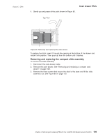
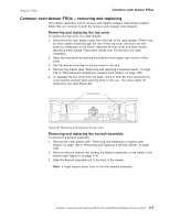
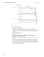
Common cash drawer FRUs Lock Actuator Rod Lock Retainer Clip August 3, 2006 Figure 91. Keylock assembly To replace the keylock assembly: 1. Ensure that the lock actuator rod is in the position shown in Figure 91. 2. Slide the lock assembly all the way into the opening in the front of the drawer, making sure that the end of the lock actuator rod is interlocked with the rear of the lock. 3. Reinstall the lock retainer clip. 4. Reinstall the drawer. Removing and replacing the latch and sensor assembly To remove the latch and sensor assembly: 1. Disconnect the cash-drawer cable from the connector at the rear of the cash drawer. 2. Remove the cash drawer (see "Removing and replacing a full-size drawer" on page 105 or "Removing and replacing a compact cash drawer" on page 108). 3. Reach in from the front and push the latch on each side of the latch assembly inward while pulling the assembly toward the front (see Figure 82 on page 107). 4. Slide the assembly out of the base. 114
-
 1
1 -
2
-
3
-
4
-
5
-
6
-
7
-
8
-
9
-
10
-
11
-
12
-
13
-
14
-
15
-
16
-
17
-
18
-
19
-
20
-
21
-
22
-
23
-
24
-
25
-
26
-
27
-
28
-
29
-
30
-
31
-
32
-
33
-
34
-
35
-
36
-
37
-
38
-
39
-
40
-
41
-
42
-
43
-
44
-
45
-
46
-
47
-
48
-
49
-
50
-
51
-
52
-
53
-
54
-
55
-
56
-
57
-
58
-
59
-
60
-
61
-
62
-
63
-
64
-
65
-
66
-
67
-
68
-
69
-
70
-
71
-
72
-
73
-
74
-
75
-
76
-
77
-
78
-
79
-
80
-
81
-
82
-
83
-
84
-
85
-
86
-
87
-
88
-
89
-
90
-
91
-
92
-
93
-
94
-
95
-
96
-
97
-
98
-
99
-
100
-
101
-
102
-
103
-
104
-
105
-
106
-
107
-
108
-
109
-
110
-
111
-
112
-
113
-
114
-
115
-
116
-
117
-
118
-
119
-
120
-
121
-
122
-
123
-
124
-
125
-
126
-
127
-
128
-
129
-
130
-
131
-
132
-
133
-
134
-
 135
135 -
 136
136 -
 137
137 -
 138
138 -
 139
139 -
 140
140 -
 141
141 -
 142
142 -
 143
143 -
 144
144 -
 145
145 -
146
-
147
-
148
-
149
-
150
-
151
-
152
-
153
-
154
-
155
-
156
-
157
-
158
-
159
-
160
-
161
-
162
-
163
-
164
-
165
-
166
-
167
-
168
-
169
-
170
-
171
-
172
-
173
-
174
-
175
-
176
-
177
-
178
-
179
-
180
-
181
-
182
-
183
-
184
-
185
-
186
-
187
-
188
-
189
-
190
-
191
-
192
-
193
-
194
-
195
-
196
-
197
-
198
-
199
-
200
-
201
-
202
-
203
-
204
-
205
-
206
-
207
-
208
-
209
-
210
-
211
-
212
-
213
-
214
-
215
-
216
-
217
-
218
-
219
-
220
-
221
-
222
-
223
-
224
-
225
-
226
-
227
-
228
-
229
-
230
-
231
-
232
-
233
-
234
-
235
-
236
-
237
-
238
-
239
-
240
-
241
-
242
-
243
-
244
-
245
-
246
-
247
-
248
-
249
-
250
-
251
-
252
-
253
-
254
-
255
-
256
-
257
-
258
 |
 |
