IBM 4840-544 Service Guide - Page 168
CANPOS, keyboard
 |
View all IBM 4840-544 manuals
Add to My Manuals
Save this manual to your list of manuals |
Page 168 highlights
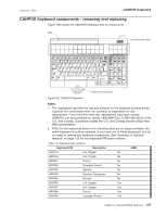
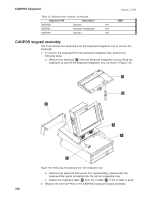
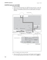
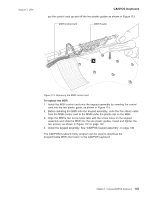
CANPOS Keyboard August 3, 2006 CANPOS keyboard with MSR To remove the MSR: 1. Remove the keypad assembly. See "CANPOS keypad assembly" on page 138. 2. Remove the two screws holding the MSR to the keypad assembly as shown in Figure 112. Lift the MSR up and off the the two plastic guides on the keypad assembly. Keypad Assembly MSR MSR control card to J2 MSR screws Ribbon Cable, to J3 Ribbon Cable, to J4 MSR connector Keyboard Logic card J2 J4 J3 Latch to J5 Ribbon Cable to MJ1 J5 J1 Ribbon Cable Connectors MJ1 Integrated Pointing Device Connector Figure 112. CANPOS keypad assembly with MSR 3. Remove the MSR control card by placing a small slotted screwdriver between the metal keypad assembly and the bottom of the MSR control card A ; and 142
-
 1
1 -
2
-
3
-
4
-
5
-
6
-
7
-
8
-
9
-
10
-
11
-
12
-
13
-
14
-
15
-
16
-
17
-
18
-
19
-
20
-
21
-
22
-
23
-
24
-
25
-
26
-
27
-
28
-
29
-
30
-
31
-
32
-
33
-
34
-
35
-
36
-
37
-
38
-
39
-
40
-
41
-
42
-
43
-
44
-
45
-
46
-
47
-
48
-
49
-
50
-
51
-
52
-
53
-
54
-
55
-
56
-
57
-
58
-
59
-
60
-
61
-
62
-
63
-
64
-
65
-
66
-
67
-
68
-
69
-
70
-
71
-
72
-
73
-
74
-
75
-
76
-
77
-
78
-
79
-
80
-
81
-
82
-
83
-
84
-
85
-
86
-
87
-
88
-
89
-
90
-
91
-
92
-
93
-
94
-
95
-
96
-
97
-
98
-
99
-
100
-
101
-
102
-
103
-
104
-
105
-
106
-
107
-
108
-
109
-
110
-
111
-
112
-
113
-
114
-
115
-
116
-
117
-
118
-
119
-
120
-
121
-
122
-
123
-
124
-
125
-
126
-
127
-
128
-
129
-
130
-
131
-
132
-
133
-
134
-
135
-
136
-
137
-
138
-
139
-
140
-
141
-
142
-
143
-
144
-
145
-
146
-
147
-
148
-
149
-
150
-
151
-
152
-
153
-
154
-
155
-
156
-
157
-
158
-
159
-
160
-
161
-
162
-
 163
163 -
 164
164 -
 165
165 -
 166
166 -
 167
167 -
 168
168 -
 169
169 -
 170
170 -
 171
171 -
 172
172 -
 173
173 -
174
-
175
-
176
-
177
-
178
-
179
-
180
-
181
-
182
-
183
-
184
-
185
-
186
-
187
-
188
-
189
-
190
-
191
-
192
-
193
-
194
-
195
-
196
-
197
-
198
-
199
-
200
-
201
-
202
-
203
-
204
-
205
-
206
-
207
-
208
-
209
-
210
-
211
-
212
-
213
-
214
-
215
-
216
-
217
-
218
-
219
-
220
-
221
-
222
-
223
-
224
-
225
-
226
-
227
-
228
-
229
-
230
-
231
-
232
-
233
-
234
-
235
-
236
-
237
-
238
-
239
-
240
-
241
-
242
-
243
-
244
-
245
-
246
-
247
-
248
-
249
-
250
-
251
-
252
-
253
-
254
-
255
-
256
-
257
-
258
 |
 |

CANPOS
keyboard
with
MSR
To
remove
the
MSR
:
1.
Remove
the
keypad
assembly.
See
“CANPOS
keypad
assembly”
on
page
138.
2.
Remove
the
two
screws
holding
the
MSR
to
the
keypad
assembly
as
shown
in
Figure
112.
Lift
the
MSR
up
and
off
the
the
two
plastic
guides
on
the
keypad
assembly.
3.
Remove
the
MSR
control
card
by
placing
a
small
slotted
screwdriver
between
the
metal
keypad
assembly
and
the
bottom
of
the
MSR
control
card
±A²
;
and
J5
J4
J3
MJ1
Latch
J1
Ribbon Cable, to J3
Ribbon Cable, to J4
Ribbon Cable to MJ1
to J5
Ribbon Cable
Connectors
Integrated Pointing
Device Connector
Keyboard Logic card
Keypad Assembly
MSR connector
J2
MSR control card
MSR
to J2
MSR screws
Figure
112.
CANPOS
keypad
assembly
with
MSR
CANPOS
Keyboard
August
3,
2006
142