IBM 4840-544 Service Guide - Page 166
locations.
 |
View all IBM 4840-544 manuals
Add to My Manuals
Save this manual to your list of manuals |
Page 166 highlights
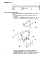
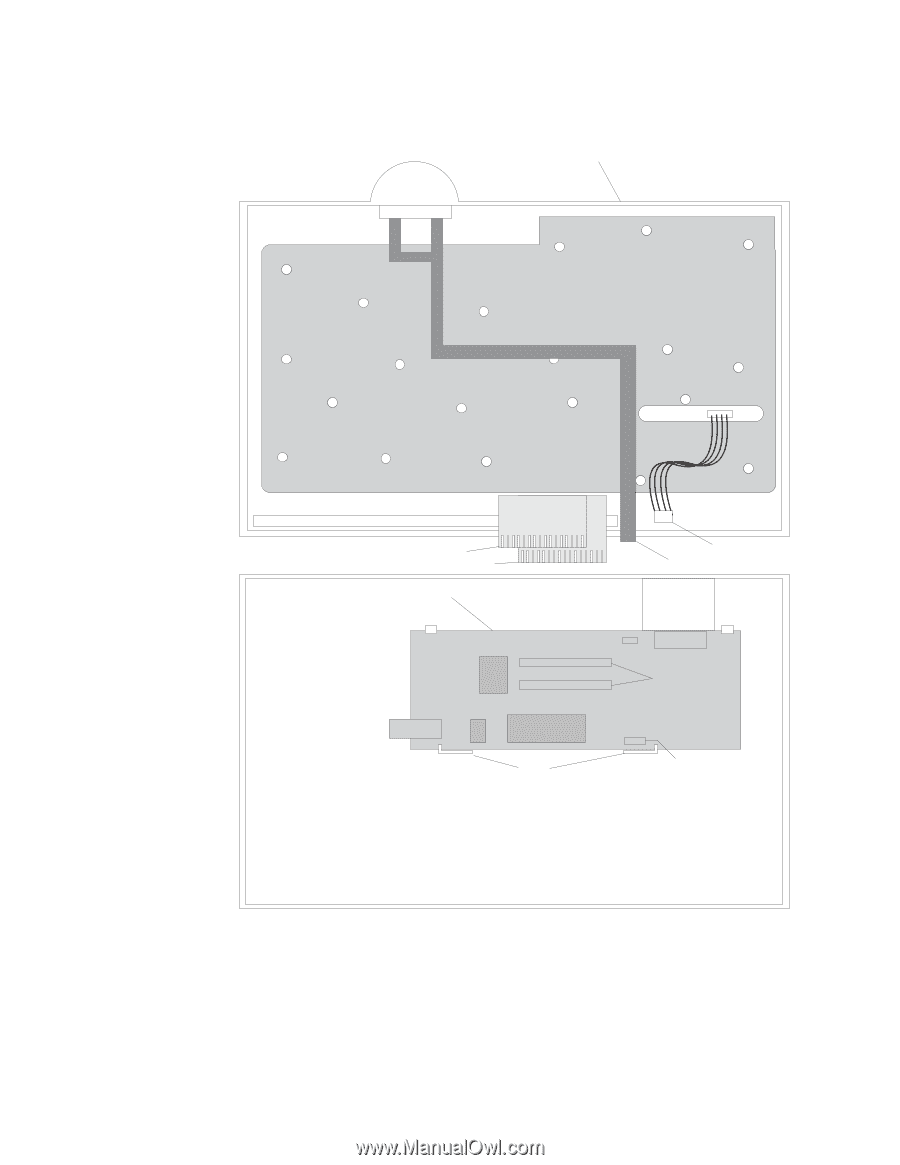
CANPOS Keyboard August 3, 2006 d. Disconnect all cables between the keypad assembly and the keyboard logic card. See Figure 111 for cable callouts and locations. Keypad Assembly Ribbon Cable, to J3 Ribbon Cable, to J4 Keyboard Logic card J4 J3 Latch to J5 Ribbon Cable to MJ1 J5 J1 Ribbon Cable Connectors MJ1 Integrated Pointing Device Connector Figure 111. CANPOS keypad assembly without MSR 3. Lift and remove the keypad assembly. To reinstall the keypad assembly, reverse these steps. 140
-
 1
1 -
2
-
3
-
4
-
5
-
6
-
7
-
8
-
9
-
10
-
11
-
12
-
13
-
14
-
15
-
16
-
17
-
18
-
19
-
20
-
21
-
22
-
23
-
24
-
25
-
26
-
27
-
28
-
29
-
30
-
31
-
32
-
33
-
34
-
35
-
36
-
37
-
38
-
39
-
40
-
41
-
42
-
43
-
44
-
45
-
46
-
47
-
48
-
49
-
50
-
51
-
52
-
53
-
54
-
55
-
56
-
57
-
58
-
59
-
60
-
61
-
62
-
63
-
64
-
65
-
66
-
67
-
68
-
69
-
70
-
71
-
72
-
73
-
74
-
75
-
76
-
77
-
78
-
79
-
80
-
81
-
82
-
83
-
84
-
85
-
86
-
87
-
88
-
89
-
90
-
91
-
92
-
93
-
94
-
95
-
96
-
97
-
98
-
99
-
100
-
101
-
102
-
103
-
104
-
105
-
106
-
107
-
108
-
109
-
110
-
111
-
112
-
113
-
114
-
115
-
116
-
117
-
118
-
119
-
120
-
121
-
122
-
123
-
124
-
125
-
126
-
127
-
128
-
129
-
130
-
131
-
132
-
133
-
134
-
135
-
136
-
137
-
138
-
139
-
140
-
141
-
142
-
143
-
144
-
145
-
146
-
147
-
148
-
149
-
150
-
151
-
152
-
153
-
154
-
155
-
156
-
157
-
158
-
159
-
160
-
 161
161 -
 162
162 -
 163
163 -
 164
164 -
 165
165 -
 166
166 -
 167
167 -
 168
168 -
 169
169 -
 170
170 -
 171
171 -
172
-
173
-
174
-
175
-
176
-
177
-
178
-
179
-
180
-
181
-
182
-
183
-
184
-
185
-
186
-
187
-
188
-
189
-
190
-
191
-
192
-
193
-
194
-
195
-
196
-
197
-
198
-
199
-
200
-
201
-
202
-
203
-
204
-
205
-
206
-
207
-
208
-
209
-
210
-
211
-
212
-
213
-
214
-
215
-
216
-
217
-
218
-
219
-
220
-
221
-
222
-
223
-
224
-
225
-
226
-
227
-
228
-
229
-
230
-
231
-
232
-
233
-
234
-
235
-
236
-
237
-
238
-
239
-
240
-
241
-
242
-
243
-
244
-
245
-
246
-
247
-
248
-
249
-
250
-
251
-
252
-
253
-
254
-
255
-
256
-
257
-
258
 |
 |
d.
Disconnect
all
cables
between
the
keypad
assembly
and
the
keyboard
logic
card.
See
Figure
111
for
cable
callouts
and
locations.
3.
Lift
and
remove
the
keypad
assembly.
To
reinstall
the
keypad
assembly,
reverse
these
steps.
J5
J4
J3
MJ1
Latch
J1
Ribbon Cable, to J3
Ribbon Cable, to J4
Ribbon Cable to MJ1
to J5
Ribbon Cable
Connectors
Integrated Pointing
Device Connector
Keyboard Logic card
Keypad Assembly
Figure
111.
CANPOS
keypad
assembly
without
MSR
CANPOS
Keyboard
August
3,
2006
140