IBM 4840-544 Service Guide - Page 93
shield, removing, replacing, System-board, battery
 |
View all IBM 4840-544 manuals
Add to My Manuals
Save this manual to your list of manuals |
Page 93 highlights
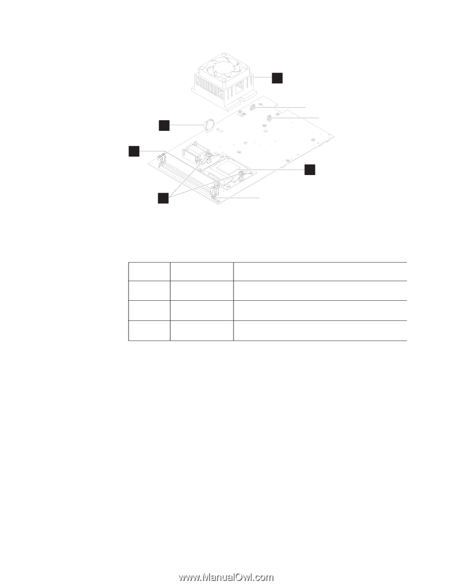
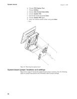
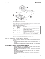
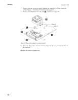
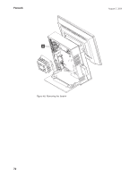
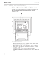
August 3, 2006 System board B A E JP32-35 JP29-31 D C JP7 Figure 46. System board jumper locations Table 8 lists the system board jumper settings. All jumper pins have the pin number printed on the system board for easy identification. Table 8. System board jumper settings Jumper Default pin location: Description JP7 pins 1-2 CMOS Memory clear - to clear CMOS, momentarily place the jumper on pins 2-3 JP29-JP35 pins 1-2 Dual video adapter - to install the dual video adapter, remove all jumpers from these pins JP6 pins 1-2 If JP6 header is populated on the system board, the jumper must remain on pins 1 and 2 at all times. Note: Pin 1 is indicated on all jumpers by a small white circle. Side I/O EMC shield - removing and replacing This part is attached to the system board, and surrounds the inside of the side I/O panel door. 1. Remove the system board. See "System board - removing and replacing" on page 65. 2. Remove the two screws attaching the side I/O EMC shield to the system board. System-board battery - removing and replacing 1. Switch OFF the power to the SurePOS 500 Models 5x3 and 544/564. Unplug the power cord from the external power source. 2. Remove the back cover as described at "Covers - removing and replacing" on page 36. 3. Remove the rear inner metal cover. See "Rear inner metal cover - removing and replacing" on page 78. 4. Remove the power supply. See "Power supply - removing and replacing" on page 57. Chapter 4. Removing and replacing FRUs for the SurePOS 500 Models 5x3 and 544/564 67
-
 1
1 -
2
-
3
-
4
-
5
-
6
-
7
-
8
-
9
-
10
-
11
-
12
-
13
-
14
-
15
-
16
-
17
-
18
-
19
-
20
-
21
-
22
-
23
-
24
-
25
-
26
-
27
-
28
-
29
-
30
-
31
-
32
-
33
-
34
-
35
-
36
-
37
-
38
-
39
-
40
-
41
-
42
-
43
-
44
-
45
-
46
-
47
-
48
-
49
-
50
-
51
-
52
-
53
-
54
-
55
-
56
-
57
-
58
-
59
-
60
-
61
-
62
-
63
-
64
-
65
-
66
-
67
-
68
-
69
-
70
-
71
-
72
-
73
-
74
-
75
-
76
-
77
-
78
-
79
-
80
-
81
-
82
-
83
-
84
-
85
-
86
-
87
-
 88
88 -
 89
89 -
 90
90 -
 91
91 -
 92
92 -
 93
93 -
 94
94 -
 95
95 -
 96
96 -
 97
97 -
 98
98 -
99
-
100
-
101
-
102
-
103
-
104
-
105
-
106
-
107
-
108
-
109
-
110
-
111
-
112
-
113
-
114
-
115
-
116
-
117
-
118
-
119
-
120
-
121
-
122
-
123
-
124
-
125
-
126
-
127
-
128
-
129
-
130
-
131
-
132
-
133
-
134
-
135
-
136
-
137
-
138
-
139
-
140
-
141
-
142
-
143
-
144
-
145
-
146
-
147
-
148
-
149
-
150
-
151
-
152
-
153
-
154
-
155
-
156
-
157
-
158
-
159
-
160
-
161
-
162
-
163
-
164
-
165
-
166
-
167
-
168
-
169
-
170
-
171
-
172
-
173
-
174
-
175
-
176
-
177
-
178
-
179
-
180
-
181
-
182
-
183
-
184
-
185
-
186
-
187
-
188
-
189
-
190
-
191
-
192
-
193
-
194
-
195
-
196
-
197
-
198
-
199
-
200
-
201
-
202
-
203
-
204
-
205
-
206
-
207
-
208
-
209
-
210
-
211
-
212
-
213
-
214
-
215
-
216
-
217
-
218
-
219
-
220
-
221
-
222
-
223
-
224
-
225
-
226
-
227
-
228
-
229
-
230
-
231
-
232
-
233
-
234
-
235
-
236
-
237
-
238
-
239
-
240
-
241
-
242
-
243
-
244
-
245
-
246
-
247
-
248
-
249
-
250
-
251
-
252
-
253
-
254
-
255
-
256
-
257
-
258
 |
 |