IBM 4840-544 Service Guide - Page 91
System, board, removing, replacing
 |
View all IBM 4840-544 manuals
Add to My Manuals
Save this manual to your list of manuals |
Page 91 highlights
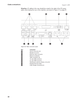
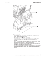
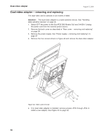
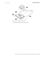
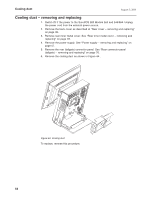
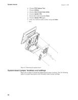
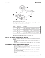
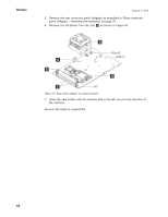
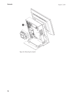
August 3, 2006 System board System board - removing and replacing Attention: Establish personal grounding before touching this unit. See "Electrostatic discharge (ESD)" on page 197. Notes: 1. The new system board comes with factory default CMOS settings. When replacing the system board, you can usually save the CMOS settings by running the SaveCMOS utility before replacing the old system board. Then, run LoadCMOS after the installation of the new system board. 2. Later versions of power supply keep the fan running when the system is connected to power, but has been powered Off. This is normal operation. Remove the system board 1. Switch OFF the power to the SurePOS 500 Models 5x3 and 544/564. Unplug the power cord from the external power source. 2. Remove the back cover as described at "Rear cover - removing and replacing" on page 38. 3. Open the side panel door. 4. Remove the power supply. See "Power supply - removing and replacing" on page 57. 5. Remove the rear inner metal cover. See "Rear inner metal cover - removing and replacing" on page 78. 6. Disconnect all cables from the system board. 7. Remove the rear connector panel (tailgate). See "Rear connector panel (tailgate) - removing and replacing" on page 76. 8. Remove the cooling duct. See "Cooling duct - removing and replacing" on page 64. 9. Remove the five screws, as shown in Figure 45 on page 66. 10. Grasp the entire assembly by the fansink and slide it out toward the top. Transfer modules to the new system board Place the assembly on a table and remove the following parts: v Memory modules - See "Memory modules - removing and replacing" on page 72. v Fansink - See "Fansink - removing and replacing" on page 69. v Processor - See "Processor module - removing and replacing" on page 71. v Dual video adapter, if installed. See "Dual-video adapter - removing and replacing" on page 62. Remove jumpers JP29-JP35 from the system board for dual video adapter installation. Install these parts on the new system board. The new system board comes with all required jumpers and with a new battery. Install the new system board Perform the system board removal steps, in reverse order. Update system software 1. Ensure system BIOS is equal to or greater than that from the old system board. See "Updating the flash BIOS" on page 22. 2. Reprogram the Vital Product Data (VPD). a. Boot the service diskette. Chapter 4. Removing and replacing FRUs for the SurePOS 500 Models 5x3 and 544/564 65
-
 1
1 -
2
-
3
-
4
-
5
-
6
-
7
-
8
-
9
-
10
-
11
-
12
-
13
-
14
-
15
-
16
-
17
-
18
-
19
-
20
-
21
-
22
-
23
-
24
-
25
-
26
-
27
-
28
-
29
-
30
-
31
-
32
-
33
-
34
-
35
-
36
-
37
-
38
-
39
-
40
-
41
-
42
-
43
-
44
-
45
-
46
-
47
-
48
-
49
-
50
-
51
-
52
-
53
-
54
-
55
-
56
-
57
-
58
-
59
-
60
-
61
-
62
-
63
-
64
-
65
-
66
-
67
-
68
-
69
-
70
-
71
-
72
-
73
-
74
-
75
-
76
-
77
-
78
-
79
-
80
-
81
-
82
-
83
-
84
-
85
-
 86
86 -
 87
87 -
 88
88 -
 89
89 -
 90
90 -
 91
91 -
 92
92 -
 93
93 -
 94
94 -
 95
95 -
 96
96 -
97
-
98
-
99
-
100
-
101
-
102
-
103
-
104
-
105
-
106
-
107
-
108
-
109
-
110
-
111
-
112
-
113
-
114
-
115
-
116
-
117
-
118
-
119
-
120
-
121
-
122
-
123
-
124
-
125
-
126
-
127
-
128
-
129
-
130
-
131
-
132
-
133
-
134
-
135
-
136
-
137
-
138
-
139
-
140
-
141
-
142
-
143
-
144
-
145
-
146
-
147
-
148
-
149
-
150
-
151
-
152
-
153
-
154
-
155
-
156
-
157
-
158
-
159
-
160
-
161
-
162
-
163
-
164
-
165
-
166
-
167
-
168
-
169
-
170
-
171
-
172
-
173
-
174
-
175
-
176
-
177
-
178
-
179
-
180
-
181
-
182
-
183
-
184
-
185
-
186
-
187
-
188
-
189
-
190
-
191
-
192
-
193
-
194
-
195
-
196
-
197
-
198
-
199
-
200
-
201
-
202
-
203
-
204
-
205
-
206
-
207
-
208
-
209
-
210
-
211
-
212
-
213
-
214
-
215
-
216
-
217
-
218
-
219
-
220
-
221
-
222
-
223
-
224
-
225
-
226
-
227
-
228
-
229
-
230
-
231
-
232
-
233
-
234
-
235
-
236
-
237
-
238
-
239
-
240
-
241
-
242
-
243
-
244
-
245
-
246
-
247
-
248
-
249
-
250
-
251
-
252
-
253
-
254
-
255
-
256
-
257
-
258
 |
 |
