IBM 4840-544 Service Guide - Page 99
Memory, modules
 |
View all IBM 4840-544 manuals
Add to My Manuals
Save this manual to your list of manuals |
Page 99 highlights
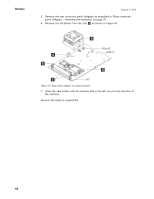
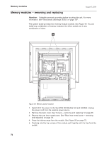
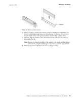
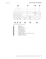
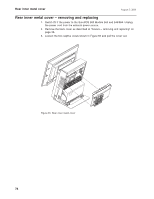
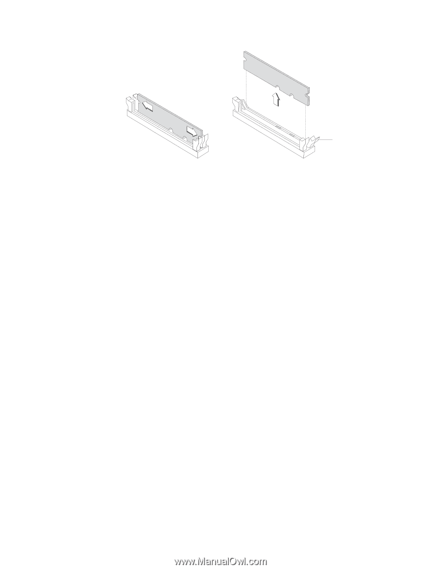
August 3, 2006 Memory modules Retainer Figure 50. Memory module removal 6. Before inserting a replacement module, note the alignment notches along the bottom of the module and where the module plugs into the slot. One notch is located in the center of the gold connectors and the other notch is offset. 7. Carefully align the module in the slot and then press it into the slot until it is secured by the clip. Note: Ensure the memory module is fully seated in the socket and the retainer tabs are fully upright and engaged in the memory module side notches. 8. Replace the components removed earlier in this procedure. Chapter 4. Removing and replacing FRUs for the SurePOS 500 Models 5x3 and 544/564 73
-
 1
1 -
2
-
3
-
4
-
5
-
6
-
7
-
8
-
9
-
10
-
11
-
12
-
13
-
14
-
15
-
16
-
17
-
18
-
19
-
20
-
21
-
22
-
23
-
24
-
25
-
26
-
27
-
28
-
29
-
30
-
31
-
32
-
33
-
34
-
35
-
36
-
37
-
38
-
39
-
40
-
41
-
42
-
43
-
44
-
45
-
46
-
47
-
48
-
49
-
50
-
51
-
52
-
53
-
54
-
55
-
56
-
57
-
58
-
59
-
60
-
61
-
62
-
63
-
64
-
65
-
66
-
67
-
68
-
69
-
70
-
71
-
72
-
73
-
74
-
75
-
76
-
77
-
78
-
79
-
80
-
81
-
82
-
83
-
84
-
85
-
86
-
87
-
88
-
89
-
90
-
91
-
92
-
93
-
 94
94 -
 95
95 -
 96
96 -
 97
97 -
 98
98 -
 99
99 -
 100
100 -
 101
101 -
 102
102 -
 103
103 -
 104
104 -
105
-
106
-
107
-
108
-
109
-
110
-
111
-
112
-
113
-
114
-
115
-
116
-
117
-
118
-
119
-
120
-
121
-
122
-
123
-
124
-
125
-
126
-
127
-
128
-
129
-
130
-
131
-
132
-
133
-
134
-
135
-
136
-
137
-
138
-
139
-
140
-
141
-
142
-
143
-
144
-
145
-
146
-
147
-
148
-
149
-
150
-
151
-
152
-
153
-
154
-
155
-
156
-
157
-
158
-
159
-
160
-
161
-
162
-
163
-
164
-
165
-
166
-
167
-
168
-
169
-
170
-
171
-
172
-
173
-
174
-
175
-
176
-
177
-
178
-
179
-
180
-
181
-
182
-
183
-
184
-
185
-
186
-
187
-
188
-
189
-
190
-
191
-
192
-
193
-
194
-
195
-
196
-
197
-
198
-
199
-
200
-
201
-
202
-
203
-
204
-
205
-
206
-
207
-
208
-
209
-
210
-
211
-
212
-
213
-
214
-
215
-
216
-
217
-
218
-
219
-
220
-
221
-
222
-
223
-
224
-
225
-
226
-
227
-
228
-
229
-
230
-
231
-
232
-
233
-
234
-
235
-
236
-
237
-
238
-
239
-
240
-
241
-
242
-
243
-
244
-
245
-
246
-
247
-
248
-
249
-
250
-
251
-
252
-
253
-
254
-
255
-
256
-
257
-
258
 |
 |
6.
Before
inserting
a
replacement
module,
note
the
alignment
notches
along
the
bottom
of
the
module
and
where
the
module
plugs
into
the
slot.
One
notch
is
located
in
the
center
of
the
gold
connectors
and
the
other
notch
is
offset.
7.
Carefully
align
the
module
in
the
slot
and
then
press
it
into
the
slot
until
it
is
secured
by
the
clip.
Note:
Ensure
the
memory
module
is
fully
seated
in
the
socket
and
the
retainer
tabs
are
fully
upright
and
engaged
in
the
memory
module
side
notches.
8.
Replace
the
components
removed
earlier
in
this
procedure.
Retainer
Figure
50.
Memory
module
removal
Memory
modules
August
3,
2006
Chapter
4.
Removing
and
replacing
FRUs
for
the
SurePOS
500
Models
5x3
and
544/564
73