Netgear GS110TP GS108Tv2/GS110TP Software Reference Manual - Page 281
VLAN Example Configuration, VLAN Configuration
 |
UPC - 606449069129
View all Netgear GS110TP manuals
Add to My Manuals
Save this manual to your list of manuals |
Page 281 highlights
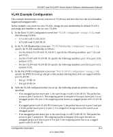
GS108T and GS110TP Smart Switch Software Administration Manual VLAN Example Configuration This example demonstrates several scenarios of VLAN use and describes how the switch handles tagged and untagged traffic. In this example, you create two new VLANs, change the port membership for default VLAN 1, and assign port members to the two new VLANs: 1. In the Basic VLAN Configuration screen (see "VLAN Configuration" on page 3-11), create the following VLANs: • A VLAN with VLAN ID 10. • A VLAN with VLAN ID 20. 2. In the VLAN Membership screen (see "VLAN Membership Configuration" on page 3-12) specify the VLAN membership as follows: • For the default VLAN with VLAN ID 1, specify the following members: port 7 (U) and port 8 (U). • For the VLAN with VLAN ID 10, specify the following members: port 1 (U), port 2 (U), and port 3 (T). • For the VLAN with VLAN ID 20, specify the following members: port 4 (U), port 5 (T), and port 6 (U). 3. In the Port PVID Configuration screen (see "Port VLAN ID Configuration" on page 3-14), specify the PVID for ports g1 and g4 so that packets entering these ports are tagged with the port VLAN ID: • Port g1: PVID 10 • Port g4: PVID 20 4. With the VLAN configuration that you set up, the following situations produce results as described: • If an untagged packet enters port 1, the switch tags it with VLAN ID 10. The packet has access to port 2 and port 3. The outgoing packet is stripped of its tag to leave port 2 as an untagged packet. For port 3, the outgoing packet leaves as a tagged packet with VLAN ID 10. • If a tagged packet with VLAN ID 10 enters port 3, the packet has access to port 1 and port 2. If the packet leaves port 1 or port 2, it is stripped of its tag to leave the switch as an untagged packet. • If an untagged packet enters port 4, the switch tags it with VLAN ID 20. The packet has access to port 5 and port 6. The outgoing packet is stripped of its tag to become an untagged packet as it leaves port 6. For port 5, the outgoing packet leaves as a tagged packet with VLAN ID 20. Configuration Examples B-3 v1.0, April 2010
-
 1
1 -
2
-
3
-
4
-
5
-
6
-
7
-
8
-
9
-
10
-
11
-
12
-
13
-
14
-
15
-
16
-
17
-
18
-
19
-
20
-
21
-
22
-
23
-
24
-
25
-
26
-
27
-
28
-
29
-
30
-
31
-
32
-
33
-
34
-
35
-
36
-
37
-
38
-
39
-
40
-
41
-
42
-
43
-
44
-
45
-
46
-
47
-
48
-
49
-
50
-
51
-
52
-
53
-
54
-
55
-
56
-
57
-
58
-
59
-
60
-
61
-
62
-
63
-
64
-
65
-
66
-
67
-
68
-
69
-
70
-
71
-
72
-
73
-
74
-
75
-
76
-
77
-
78
-
79
-
80
-
81
-
82
-
83
-
84
-
85
-
86
-
87
-
88
-
89
-
90
-
91
-
92
-
93
-
94
-
95
-
96
-
97
-
98
-
99
-
100
-
101
-
102
-
103
-
104
-
105
-
106
-
107
-
108
-
109
-
110
-
111
-
112
-
113
-
114
-
115
-
116
-
117
-
118
-
119
-
120
-
121
-
122
-
123
-
124
-
125
-
126
-
127
-
128
-
129
-
130
-
131
-
132
-
133
-
134
-
135
-
136
-
137
-
138
-
139
-
140
-
141
-
142
-
143
-
144
-
145
-
146
-
147
-
148
-
149
-
150
-
151
-
152
-
153
-
154
-
155
-
156
-
157
-
158
-
159
-
160
-
161
-
162
-
163
-
164
-
165
-
166
-
167
-
168
-
169
-
170
-
171
-
172
-
173
-
174
-
175
-
176
-
177
-
178
-
179
-
180
-
181
-
182
-
183
-
184
-
185
-
186
-
187
-
188
-
189
-
190
-
191
-
192
-
193
-
194
-
195
-
196
-
197
-
198
-
199
-
200
-
201
-
202
-
203
-
204
-
205
-
206
-
207
-
208
-
209
-
210
-
211
-
212
-
213
-
214
-
215
-
216
-
217
-
218
-
219
-
220
-
221
-
222
-
223
-
224
-
225
-
226
-
227
-
228
-
229
-
230
-
231
-
232
-
233
-
234
-
235
-
236
-
237
-
238
-
239
-
240
-
241
-
242
-
243
-
244
-
245
-
246
-
247
-
248
-
249
-
250
-
251
-
252
-
253
-
254
-
255
-
256
-
257
-
258
-
259
-
260
-
261
-
262
-
263
-
264
-
265
-
266
-
267
-
268
-
269
-
270
-
271
-
272
-
273
-
274
-
275
-
 276
276 -
 277
277 -
 278
278 -
 279
279 -
 280
280 -
 281
281 -
 282
282 -
 283
283 -
 284
284 -
 285
285 -
 286
286 -
287
-
288
-
289
-
290
-
291
-
292
-
293
-
294
-
295
-
296
-
297
-
298
-
299
-
300
-
301
-
302
 |
 |
