Yamaha M7CL M7cl V1 Owner's Manual
Yamaha M7CL Manual
 |
View all Yamaha M7CL manuals
Add to My Manuals
Save this manual to your list of manuals |
Yamaha M7CL manual content summary:
- Yamaha M7CL | M7cl V1 Owner's Manual - Page 1
Owner's Manual EN - Yamaha M7CL | M7cl V1 Owner's Manual - Page 2
PROCEDURE) Responsible Party : Yamaha Corporation of America Address : 6600 Orangethorpe Ave., Buena Park, Calif. 90620 Telephone : 714-522-9011 Type of Equipment : DIGITAL MIXING CONSOLE Model Name : M7CL-48, M7CL-32 This device complies with Part 15 of the FCC Rules. Operation is subject to the - Yamaha M7CL | M7cl V1 Owner's Manual - Page 3
alert the user to the presence of important operating and maintenance (servicing) instructions in the literature accompanying the product. IMPORTANT SAFETY INSTRUCTIONS 1 Read these instructions. 2 Keep these instructions. 3 Heed all warnings. 4 Follow all instructions. 5 Do not use this apparatus - Yamaha M7CL | M7cl V1 Owner's Manual - Page 4
loss of sound during use of the device, or if any unusual smells or smoke should appear to be caused by it, immediately turn off the power switch, disconnect the electric plug from the outlet, and have the device inspected by qualified Yamaha service personnel. • If this device power supply should be - Yamaha M7CL | M7cl V1 Owner's Manual - Page 5
destroyed. Always turn the power off when the device is not in use. The performance of components with moving contacts, such as switches, volume controls, and connectors, deteriorates over time. Consult qualifi ed Yamaha service personnel about replacing defective components. This product contains - Yamaha M7CL | M7cl V1 Owner's Manual - Page 6
M7CL-48 and M7CL-32... 11 The M7CL's channel structure 13 About the MIX bus types (VARI / FIXED 14 About word clock 14 Conventions in this manual 14 About the firmware version 14 2. Panels and controls 15 Top panel 15 Rear panel 22 Under the front pad 24 3. Basic operation of the M7CL - Yamaha M7CL | M7cl V1 Owner's Manual - Page 7
151 15. Meters 153 Operations in the METER screen 153 Using the MBM7CL meter bridge (option 155 16. Graphic EQ and effects 157 About the virtual rack 157 Virtual rack operations 158 Graphic EQ operations 161 About the graphic EQ 161 Inserting a GEQ in a channel 161 Using the 31 Band - Yamaha M7CL | M7cl V1 Owner's Manual - Page 8
that can be assigned to control changes 245 Control change parameter assignments 247 NRPN parameter assignments 249 Mixing parameter operation applicability 252 Functions that can be assigned to user-defined keys 253 MIDI Data Format 255 Warning/Error Messages 262 Troubleshooting 264 General - Yamaha M7CL | M7cl V1 Owner's Manual - Page 9
simple and intuitive operation. A dedicated channel strip with fader, cue, and on/off control is provided for all frequently-used input channels and the STEREO/MONO channels. This mixer can be comfortably operated even by users who are new to digital consoles. The SELECTED CHANNEL section located at - Yamaha M7CL | M7cl V1 Owner's Manual - Page 10
or digital I/O cards can be installed in these slots to add inputs and outputs. If an external head amp unit (such as the Yamaha AD8HR) that supports a special protocol is connected to the REMOTE connector, the phantom power and gain settings of the external head amp can also be remotely controlled - Yamaha M7CL | M7cl V1 Owner's Manual - Page 11
to the channel strip for INPUT channels 1-32 located at the left side of the front panel, there is a channel strip for INPUT channels 33-48 located at the right side of the front panel. 1 1 Channel strip for INPUT channels 1-32 B Channel strip for INPUT channels 33-48 2 M7CL Owner's Manual 11 - Yamaha M7CL | M7cl V1 Owner's Manual - Page 12
the front panel, just as on the M7CL-48 model, but there is no channel strip for INPUT channels in the right side. 1 1 Channel strip for INPUT channels 1-32 HINT • In this owner's manual, whenever there is a difference between the M7CL-32 model and the M7CL-48 model, specifications that apply only to - Yamaha M7CL | M7cl V1 Owner's Manual - Page 13
that are sent from the input channels or MIX channels, and send them to the corresponding output port. These channels are used as the main stereo output and monaural output. ● INPUT channels 1-32 {1-48} The STEREO channel and MONO channel can be used either to output independent signals, or - Yamaha M7CL | M7cl V1 Owner's Manual - Page 14
model are enclosed in curly brackets { } (e.g., INPUT jacks 1-32 {1-48}). About the firmware version You can view the firmware version number in the SETUP screen (→ p. 207). You can also download the most recent firmware version from the website. http://www.yamahaproaudio.com/ 14 M7CL Owner's Manual - Yamaha M7CL | M7cl V1 Owner's Manual - Page 15
the names and functions of each part of the M7CL. Panels and controls Top panel The top panel of the M7CL is divided into the following sections. Display section (P. 18) SELECTED CHANNEL section (P. 17) Meter bridge (option) (P. 17) SCENE MEMORY/ MONITOR section (P. 19) INPUT section (P. 16 - Yamaha M7CL | M7cl V1 Owner's Manual - Page 16
FADER mode, this is an on/off switch for the signal sent from each channel to the currently selected MIX bus. E Fader Adjusts the input level of the channel. In SENDS ON FADER mode, this adjusts the send level of the signal from each channel to the currently selected MIX bus. 16 M7CL Owner's Manual - Yamaha M7CL | M7cl V1 Owner's Manual - Page 17
■ Meter bridge (option) If an optional MBM7CL meter bridge is installed, the 1 MIX meters MIX/MATRIX channel levels can be monitored at all These indicate the level of MIX channels 1-16. times. The monitoring position can be selected from PRE EQ (immediately before attenuator), PRE FADER (imme - Yamaha M7CL | M7cl V1 Owner's Manual - Page 18
2 1 Display (touch screen) This display shows the information you need to operate the M7CL, and lets you make system-wide settings and control mix parameters for input and output channels. Since this is a touch screen, you can use your finger on the screen to select menus or set parameters. However - Yamaha M7CL | M7cl V1 Owner's Manual - Page 19
/output level of the channel. You can also make internal settings (→ p. 163) so that these faders are used as controllers to adjust the gain of each GEQ band. ■ SCENE MEMORY/MONITOR section In this section you can perform operations for scene memory and monitoring. 1 24 3 1 SCENE MEMORY [STORE - Yamaha M7CL | M7cl V1 Owner's Manual - Page 20
time you press the [SEL] key. B [CUE] key This key selects the channel to be cue-monitored. If cue is on, the LED will light. C [ON] key This key switches the channel on/off. If a channel is on, the key LED will light. D Fader This adjusts the output level of the channel. 20 M7CL Owner's Manual - Yamaha M7CL | M7cl V1 Owner's Manual - Page 21
of the Centralogic section. In this case, modules 4-8 are not used. K [IN 33-40] key {M7CL-48 only} 1 25 JK 67 L [IN 41-48] key {M7CL-48 only} These keys select INPUT channels 33-40 and 41-48 respectively. 1 [IN 1-8] key B [IN 9-16] key C [IN 17-24] key D [IN 25-32] key These keys select INPUT - Yamaha M7CL | M7cl V1 Owner's Manual - Page 22
output jack that supplies power to a separately sold gooseneck lamp (such as the Yamaha LA5000). {The M7CL-48 has these connectors at two locations.} 9 8 7 6 5 E 2TR OUT DIGITAL jack This is an AES/EBU (XLR-3-32 male) jack that outputs the digital audio signal of a desired channel in AES/EBU - Yamaha M7CL | M7cl V1 Owner's Manual - Page 23
to control mix parameters or edit scene memories and libraries from the dedicated "M7CL Editor" application program. NOTE • The DME Network Driver required for connection to the Ethernet connector, the Studio Manager required for starting up M7CL Editor, and the M7CL Editor itself can be downloaded - Yamaha M7CL | M7cl V1 Owner's Manual - Page 24
you monitor the MONITOR OUT or CUE signal. C TALKBACK jack This is a balanced XLR-3-31 jack to which a talkback mic can be connected. You can make settings in the screen to supply +48V phantom power to this jack. This is used to send instructions from the mixer operator to the desired output channel - Yamaha M7CL | M7cl V1 Owner's Manual - Page 25
Chapter 3 Basic operation of the M7CL Basic operation of the M7CL This chapter explains the M7CL's user interface and its basic operations. 3 Basic operations in the top panel / touch screen This section explains the basic procedures you can perform in the M7CL's top panel and touch screen. In - Yamaha M7CL | M7cl V1 Owner's Manual - Page 26
the touch screen to select the knob you want to operate. Using the multifunction encoders to control parameters. The on-screen user interface Operations such as mixing and adjusting the sound of each channel are performed using the top panel faders, keys, and encoders. However to make more detailed - Yamaha M7CL | M7cl V1 Owner's Manual - Page 27
The on-screen user interface Faders / Knobs Faders in the screen are used mainly for visual confirmation of the levels of the corresponding channels, and will move in tandem when you operate the top panel faders. The current value is also shown in numerical form immediately below the fader. List - Yamaha M7CL | M7cl V1 Owner's Manual - Page 28
will select the next channel. J K Function access area B Time This indicates the current time. (For details on how to set the time → p. 213). C User name This indicates the name of the user who is currently logged in (i.e., is authenticated and able to operate the system). 28 M7CL Owner's Manual - Yamaha M7CL | M7cl V1 Owner's Manual - Page 29
on-line help in the main area. However, the current software as of September 2005 does not support this. E SENDS ON FADER Press this button to switch to SENDS ON FADER mode, where you can use the faders of the top panel to adjust the MIX send level (→ p. 64). During this time, the function access - Yamaha M7CL | M7cl V1 Owner's Manual - Page 30
boxes, and in the PATCH/NAME window you can use this to switch channels. ● SHIFT LOCK button Switches between uppercase and lowercase name you entered. In the SCENE STORE window, this has the same effect as pressing the STORE button. The box that shows the characters you've . 30 M7CL Owner's Manual - Yamaha M7CL | M7cl V1 Owner's Manual - Page 31
Specifies POST as the position from which all signals are sent to the specified bus. Using libraries 3 This section explains basic operations for libraries. Librar- ies allow you to store and recall settings for the currently selected channel (EQ/dynamics) or rack (GEQ/effect). Basic operation - Yamaha M7CL | M7cl V1 Owner's Manual - Page 32
window (1 ch)] [DYNAMICS 1/2 popup window (1 ch)] Use the panel [SEL] keys or the channel select button in the function access area to select a channel. Channel select button 1 EQ graph field B Dynamics 1/2 field [GEQ/EFFECT popup window] In the VIRTUAL RACK window that appears when you press the - Yamaha M7CL | M7cl V1 Owner's Manual - Page 33
name buttons in the 8 ch/ALL popup window, you can select multiple channels by selecting a region. In this case, the same library data will be recalled to all of the selected channels. Selected region [GEQ/EFFECT popup window] Use the rack select tabs at the bottom of the popup window to select - Yamaha M7CL | M7cl V1 Owner's Manual - Page 34
rack (GEQ/effect) whose settings you want to store. NOTE • You can select only one channel or rack as the source for storing. If multiple channels are selected in the dynamics/EQ popup window (8 ch or ALL), you won't be able to perform the Store operation. 3 In the upper part 34 M7CL Owner's Manual - Yamaha M7CL | M7cl V1 Owner's Manual - Page 35
The EQ/dynamics of the channel or the effect settings of the rack you selected in step 2 will be initialized. If you decide to cancel the initialization, press the CANCEL button instead of the OK button. HINT • In the case of EQ/dynamics, you can use the channel number / channel name buttons in the - Yamaha M7CL | M7cl V1 Owner's Manual - Page 36
EQ/dynamics settings, you can use the 8 ch/ ALL popup window to select multiple channels as the pastedestination. In this case, the same content will be pasted to all selected channels. 5 Press the PASTE button. The settings of the channel (EQ/dynamics) or the rack (GEQ/effect) you selected in step - Yamaha M7CL | M7cl V1 Owner's Manual - Page 37
with the settings held in the buffer memory. Unlike the Paste operation, the Compare operation always lets you return to the previous settings as long as memory can also be used for the Paste operation. NOTE • Of the two types of GEQ, using the tool buttons in a rack where a Flex15GEQ is selected - Yamaha M7CL | M7cl V1 Owner's Manual - Page 38
38 M7CL Owner's Manual - Yamaha M7CL | M7cl V1 Owner's Manual - Page 39
first time. 4 Connections ■ Analog input connections Connections and setup REC SONG SCENE MUSIC PRODUCTION SYNTHESIZER Integrated Sampling Sequencer Real-time External Control Surface Modular Synthesis Plug-in System INPUT jacks 1-32 {1-48} are used mainly to connect microphones or monaural line - Yamaha M7CL | M7cl V1 Owner's Manual - Page 40
(foldback) Power cable Main speakers Monitor speakers To the OMNI OUT jacks 1-16, you can patch the output signals from output channels (MIX, MATRIX, STEREO (L/R), MONO (C)), monitor signals (MONITOR OUT L/R/C channel), and the direct out signals of INPUT channels 1-32 {1-48}. When the M7CL is - Yamaha M7CL | M7cl V1 Owner's Manual - Page 41
(e.g., Yamaha DME64N) Main speakers Use the 2TR OUT DIGITAL jack to send the M7CL's internal signals to an external digital audio device. When the M7CL is in the default state, the output signal of the STEREO channel is patched to the 2TR OUT DIGITAL jack, and can be used to record the main mix onto - Yamaha M7CL | M7cl V1 Owner's Manual - Page 42
included with the card to fasten the card in place. Malfunctions or incorrect operation may occur if the card is not fastened. CAUTION • Before connecting a separately sold mini-YGDAI I/O card to the M7CL, you must turn off the power switch of the M7CL and the PC800W power supply. Failure to observe - Yamaha M7CL | M7cl V1 Owner's Manual - Page 43
ways in which the M7CL can operate as a word clock slave that is synchronized to an externally-sup- plied word clock; the M7CL can use the clock data included in the digital audio signal being input from a dig- ital I/O card, or it can use a separate word clock signal supplied to the rear panel - Yamaha M7CL | M7cl V1 Owner's Manual - Page 44
CLOCK IN button. If the M7CL is operating correctly with the new clock, the symbol immediately above the corresponding button will turn light blue. HINT • The clock data of the digital audio signal supplied via a digital I/O card in slots 1-3 can be selected in two-channel units. • For details on - Yamaha M7CL | M7cl V1 Owner's Manual - Page 45
• In actuality, you can use the encoders of the SELECTED CHANNEL section to operate the channel selected by its [SEL] key even without displaying the SELECTED CHANNEL VIEW screen. (In this case, a popup window will appear to show the value of the parameter you're operating.) M7CL Owner's Manual 45 - Yamaha M7CL | M7cl V1 Owner's Manual - Page 46
shown simultaneously. You can use the keys and faders of the Centralogic section to control the level, on/off status, and cue operations of the selected eight channels or DCA groups. 1 2 3 4 5 6 1 Multi-function encoders B [SEL] keys C [CUE] keys D Level meters E [ON] keys F Faders HINT • You can - Yamaha M7CL | M7cl V1 Owner's Manual - Page 47
the main speakers are appropriate. In this case as well, you can either use the SELECTED 4 CHANNEL section to make settings for one channel at a time, or use the Centralogic section to make settings for up to eight channels at a time. Connections and setup 1 HA/PHASE field 3 Press a knob in - Yamaha M7CL | M7cl V1 Owner's Manual - Page 48
connected to your speaker system. Check the output port patching (→ p. 95). ● If the LR meters are not moving It may be that the INPUT channel [ON] key is off. Check the status of the [ON] key (→ p. 16). 48 M7CL Owner's Manual 1 1 TO STEREO/MONO field 2 Make sure that in the TO STEREO/MONO field of - Yamaha M7CL | M7cl V1 Owner's Manual - Page 49
in the TO STEREO/MONO field of the OVERVIEW screen will also turn. 7 Use the navigation keys to switch the eight channels controlled by the Centralogic section, and make adjustments for other input channels in the same way. Setting up to use the M7CL 4 Connections and setup M7CL Owner's Manual 49 - Yamaha M7CL | M7cl V1 Owner's Manual - Page 50
50 M7CL Owner's Manual - Yamaha M7CL | M7cl V1 Owner's Manual - Page 51
1-3, and sends them to the STEREO bus, MONO bus, MIX buses, and MATRIX buses. There are two types of input channel, as follows. Input channel operations ■ INPUT channels 1-32 {1-48} These channels are used to process monaural signals. When the M7CL is in the default state, the input signals from - Yamaha M7CL | M7cl V1 Owner's Manual - Page 52
directly from that output port. As the position of the direct output, you can choose immediately before HPF, immediately before ATT, or immediately before fader. ● METER This meters the level of the input channel. You can switch the position at which the level is detected. 52 M7CL Owner's Manual - Yamaha M7CL | M7cl V1 Owner's Manual - Page 53
1 Use the navigation keys to access the OVERVIEW screen containing the input channel whose channel name / icon you want to assign. 3 To select the icon for that channel, press the icon button. The lower part of the popup window will change as follows. 1 5 1 Input channel operations 2 1 Channel - Yamaha M7CL | M7cl V1 Owner's Manual - Page 54
keyboard window will appear in the lower part of the window, allowing you to enter or edit the characters. For details on how to use the keyboard window, refer to p. 30. 7 Use the [SEL] keys to switch input channels, and specify the icon or channel name for other channels in the same way. When the - Yamaha M7CL | M7cl V1 Owner's Manual - Page 55
such as phantom power on/off or phase, use the navigation keys to access the OVERVIEW screen that includes the input channel whose HA you want to edit. 1 NOTE • If you've turned off the phantom power master setting in the SETUP screen SYSTEM SETUP field, phantom power will not be supplied even if - Yamaha M7CL | M7cl V1 Owner's Manual - Page 56
. C +48V button This switches the phantom power on (red) or off (black) for the head amp assigned to this channel. D GAIN knob This indicates the gain of the head amp assigned to this channel. Use multifunction encoders 1-8 to adjust the value. The level meter located at the immediate right of the - Yamaha M7CL | M7cl V1 Owner's Manual - Page 57
the monitor source before you continue with the following procedure (→ p. 142). 1 Make sure that an input source is connected to the input channel you're adjusting, and set the phantom power supply, gain, and phase of the head amp to obtain the optimum input signal (→ p. 55). 2 Use the navigation - Yamaha M7CL | M7cl V1 Owner's Manual - Page 58
window. 5 Use the MODE button to select either ST/ MONO mode or LCR mode for each channel. 6 In the STEREO / MONO MASTER section of the top panel, make sure that the [ON] key of the STEREO channel / MONO channel is turned on, and raise the fader to an appropriate position. 58 M7CL Owner's Manual - Yamaha M7CL | M7cl V1 Owner's Manual - Page 59
you want to control, and raise the fader to an appropriate position. The subsequent steps will differ depending on whether ST/MONO mode or LCR mode was selected for the channel in step 5. ● Channels for which ST/MONO mode is selected 8 In the TO STEREO/MONO popup window, use the STEREO/MONO button - Yamaha M7CL | M7cl V1 Owner's Manual - Page 60
to the MONO (C) bus Signal sent from the ST IN (L) channel to the STEREO (L) bus L C R TO ST BALANCE knob Signal level Signal sent from the ST IN (R) channel to the MONO (C) bus Signal sent from the ST IN (R) channel to the STEREO (R) bus L C R TO ST BALANCE knob 60 M7CL Owner's Manual - Yamaha M7CL | M7cl V1 Owner's Manual - Page 61
to SENDS ON FADER mode, and use the faders of the top panel to adjust the send levels to the MIX buses. When using this method, the signals sent from all input channels to a specific MIX bus can be adjusted simultaneously. Input channel operations Using the SELECTED CHANNEL section Here's how you - Yamaha M7CL | M7cl V1 Owner's Manual - Page 62
as a stereo bus and link the main parameters (→ p. 212). If the send-destination MIX bus is assigned as stereo, the left knob of the two adjacent TO MIX SEND LEVEL knobs will operate as the TO MIX PAN knob (for a ST IN channel, it will operate as the TO MIX BALANCE knob). 62 M7CL Owner's Manual - Yamaha M7CL | M7cl V1 Owner's Manual - Page 63
through MIX buses 1-16 and MATRIX buses 1-8. C Channel select button This indicates the channel number, the icon selected for that channel, and the channel name. When you press this button, that channel will be selected for operations, and the corresponding [SEL] key will light. M7CL Owner's Manual - Yamaha M7CL | M7cl V1 Owner's Manual - Page 64
) Here's how you can use the faders of the top panel to adjust the signal that is sent from all input channels to a specific MIX bus. 1 Make sure that an output port is assigned to each MIX bus to which you want to send signals, and that your monitor system or external effect etc. is connected to - Yamaha M7CL | M7cl V1 Owner's Manual - Page 65
same way. 6 When you're finished adjusting the MIX send levels, press the "×" symbol in the function access area. The function access area display will return to its prior state, and the M7CL will exit SENDS ON FADER mode and return to normal mode. 5 Input channel operations M7CL Owner's Manual 65 - Yamaha M7CL | M7cl V1 Owner's Manual - Page 66
This section explains how to send the signal from an input channel to MATRIX buses 1-8. The MATRIX buses are used to produce a mix that is independent of the STEREO bus or MIX buses, mainly for sending to a master recorder or to the monitor system for the musicians. You can send a signal from an - Yamaha M7CL | M7cl V1 Owner's Manual - Page 67
navigation keys to access the OVERVIEW screen that includes the input channel you want to control. In the OVERVIEW screen, you can use the TO MIX/ TO MATRIX field to adjust the send levels to the MIX/MATRIX bus. Input channel operations 1 2 1 TO MIX/TO MATRIX field In this field you can switch the - Yamaha M7CL | M7cl V1 Owner's Manual - Page 68
the PRE EQ (Immediately before the attenuator) or PRE FADER (Immediately before the fader) as specified in the BUS SETUP popup window if this button is on. E TO MATRIX SEND ON/OFF button These are on/off switches for the signal sent from the input channels to the MATRIX bus. 68 M7CL Owner's Manual - Yamaha M7CL | M7cl V1 Owner's Manual - Page 69
channel operations ■ MIX channels 1-16 These channels process the signals sent from input channels to MIX buses, and output them to the corresponding output port, MATRIX bus, STEREO bus, or MONO (C) bus. When the M7CL is in the default state, the following output ports are assigned. MIX channels - Yamaha M7CL | M7cl V1 Owner's Manual - Page 70
. ● METER This meters the level of the output channel. You can switch the position at which the level is detected. ● KEY IN (MIX channels 13-16 only) You can send the output signals of MIX channels 13-16 to dynamics processors and use them as key-in signals to control the dynamics. ● RACK IN PATCH - Yamaha M7CL | M7cl V1 Owner's Manual - Page 71
. 1 Use the navigation keys to access the OVERVIEW screen that includes the output channel whose channel name and icon you want to specify. 1 3 To select the icon for the channel, press the icon button. The lower part of the popup window will change as follows. 1 6 2 Output channel operations - Yamaha M7CL | M7cl V1 Owner's Manual - Page 72
operate output channels other than those in the currently selected eight channels, use the navigation keys → Centralogic section [SEL] keys to select the desired channel. 8 When you're finished with your input, press the "×" symbol in the upper right of the window. Sending signals from MIX channels - Yamaha M7CL | M7cl V1 Owner's Manual - Page 73
(ALL)] This shows the status of the signals sent from all MIX channels to the STEREO bus / MONO bus, and adjusts the pan or balance for the eight selected channels. For MATRIX channels and STEREO/MONO channels, only the channel number, icon, and channel name are shown. 13 3 2 M7CL Owner's Manual 73 - Yamaha M7CL | M7cl V1 Owner's Manual - Page 74
is turned on, and raise the fader to an appropriate position. 6 Press the [MIX 1-8] key or [MIX 9-16] key so that the MIX channels you want to control are recalled to the Centralogic section. 7 Make sure that the [ON] key of that channel is on, and use the fader in the Centralogic section to raise - Yamaha M7CL | M7cl V1 Owner's Manual - Page 75
buses. This method allows you to simultaneously control the signals sent from up to eight MIX, STEREO (L/R), or MONO (C) channels to a specific MATRIX bus. 6 Output channel operations Using the SELECTED CHANNEL section Use the encoders of the SELECTED CHANNEL section to adjust the send level of - Yamaha M7CL | M7cl V1 Owner's Manual - Page 76
access the OVERVIEW screen that includes the channel (MIX channels 1-8, 9-16, or STEREO/ MONO channels) that you want to control. In the OVERVIEW screen, you can use the TO MATRIX field to adjust the send levels to the MATRIX bus. 1 2 1 TO MATRIX field This field specifies the send level of the signal - Yamaha M7CL | M7cl V1 Owner's Manual - Page 77
from the MIX or STEREO/MONO channel to the MATRIX bus. To adjust the level, operate multifunction encoders fader position when this button is on. E TO MATRIX SEND ON/OFF button This is an on/off switch for the signal sent from the MIX or STEREO/MONO channel to the MATRIX bus. M7CL Owner's Manual - Yamaha M7CL | M7cl V1 Owner's Manual - Page 78
78 M7CL Owner's Manual - Yamaha M7CL | M7cl V1 Owner's Manual - Page 79
use the encoders on the panel to control mix parameters such as head amp gain, HPF/ EQ settings, the threshold setting of the dynamics processors, pan/balance settings, and send levels to the MIX/MATRIX buses. Operations in the SELECTED CHANNEL section SELECTED CHANNEL section M7CL Owner's Manual - Yamaha M7CL | M7cl V1 Owner's Manual - Page 80
. This screen lets you check the settings being controlled by the encoders of the SELECTED CHANNEL section. The SELECTED CHANNEL VIEW screen contains the following items. 1 7 23 4 5 6 I J K L 8 M NO 1 TO MIX/TO MATRIX field • When an input channel is selected ...........Here you can switch the - Yamaha M7CL | M7cl V1 Owner's Manual - Page 81
section explains how you can use the SELECTED CHANNEL section to control all of the parameters for a specific channel. Operations in the SELECTED CHANNEL section 1 Use a [SEL] key to select the channel you want to control. The SELECTED CHANNEL section controls the channel that was last selected by - Yamaha M7CL | M7cl V1 Owner's Manual - Page 82
values, use the corresponding [MIX/ MATRIX] encoder of the SELECTED CHANNEL section. If the send-destination MIX bus / MATRIX bus is set to stereo, the left knob of the two adjacent knobs will operate as a PAN knob. (For a ST IN channel, a stereo MIX channel, or STEREO channel, it will operate as - Yamaha M7CL | M7cl V1 Owner's Manual - Page 83
an overall on/off switch for the signals sent from the channel to the STEREO bus and MONO bus. To adjust the pan/balance of each channel, use the ST/ MONO button or LCR button to select the send-destination bus, and operate the [PAN] encoder of the SELECTED CHANNEL section. M7CL Owner's Manual 83 - Yamaha M7CL | M7cl V1 Owner's Manual - Page 84
Operations in the SELECTED CHANNEL section ● Changing the output patching (output channels only) To change the output patching of an output channel in the SELECTED CHANNEL VIEW screen, use the popup button in the PATCH field. When you press the popup button, the PATCH/NAME popup window will appear, - Yamaha M7CL | M7cl V1 Owner's Manual - Page 85
as an on/off switch for the Low Pass Filter. ● Making insert settings (INPUT, MIX, MATRIX, STEREO, and MONO channels only) Use the INSERT field to make insert-related settings for an input channel in the SELECTED CHANNEL VIEW screen. This field includes the following items. 2 13 1 INSERT popup button - Yamaha M7CL | M7cl V1 Owner's Manual - Page 86
FADER field, that channel will be switched on/off and the top panel [ON] key will operate in tandem with this. ● Assigning a channel to a DCA group (input channels only) Use the DCA field of the SELECTED CHANNEL VIEW screen to assign a channel can select the channels that will be assigned to each - Yamaha M7CL | M7cl V1 Owner's Manual - Page 87
section When you press one of the navigation keys in the NAVIGATION KEYS section, the channels / DCA groups corresponding to that key will be assigned to the Centralogic section, and can be controlled using the faders, [ON] keys, and [CUE] keys of the Centralogic section. M7CL Owner's Manual 87 - Yamaha M7CL | M7cl V1 Owner's Manual - Page 88
displayed. In this case, the Centralogic section faders and [ON] keys will control DCA group operations, and the multifunction encoders and [SEL]/[CUE] keys will control the up to eight channels shown in the OVERVIEW screen. 88 M7CL Owner's Manual J K L 1 Channel number / Channel name field This - Yamaha M7CL | M7cl V1 Owner's Manual - Page 89
the M7CL, you can leave the channels/groups assigned 8 to the Centralogic section fixed, and switch only the eight- channel groups displayed in the OVERVIEW screen (→ p. 94), and the content shown in A and L will differ in this case as well. Operations in the Centralogic section 9 I FROM MIX field - Yamaha M7CL | M7cl V1 Owner's Manual - Page 90
includes the following items. 12 90 M7CL Owner's Manual 3 1 GAIN knob This indicates the gain of the head amp assigned to the channel. To adjust the value, press the knob to select it, and operate multifunction encoders 1-8. B +48V This indicates the phantom power on (red) or off (black) status - Yamaha M7CL | M7cl V1 Owner's Manual - Page 91
Operations in the Centralogic section If the channel is patched to an input port that has no head amp, or to the rack (internal effect or GEQ), the port name, number, and phase are shown. If you want to switch the phantom power on/off, switch the phase between normal/reverse, or change the input - Yamaha M7CL | M7cl V1 Owner's Manual - Page 92
to stereo, the left of the two adjacent knobs will operate as the TO MIX PAN or TO MATRIX PAN knob (or as the BALANCE knob if the send-source channel is stereo). TO MIIX PAN/ TO MATRIX PAN knob 92 M7CL Owner's Manual 1 FROM MIX SEND LEVEL knob For each MATRIX bus, this shows the - Yamaha M7CL | M7cl V1 Owner's Manual - Page 93
indicator (INPUT, ST IN, MIX channels only) The LCR indicator shows the overall on/off status of the signals sent from that channel to the STEREO (L/ R) bus and MONO (C) bus. To switch this on/off, press the selected knob once again to open the TO STEREO/MONO popup window. M7CL Owner's Manual 93 - Yamaha M7CL | M7cl V1 Owner's Manual - Page 94
NOTE • You cannot operate DCA groups in the OVERVIEW screen using the multifunction encoders. For this reason, pressing the [DCA] key in step 2 will have no effect. Control DCA groups 1-8. 3 As desired, use the navigation keys to switch the group of eight channels controlled by the OVERVIEW screen - Yamaha M7CL | M7cl V1 Owner's Manual - Page 95
ports shown in the popup window. Each tab corresponds to the following output ports. ● OMNI/2TR OUT OMNI OUT jacks 1-16 and the 2TR OUT DIGITAL jack will be displayed. ● SLOT 1-SLOT 3 Output channels 1-16 of slots 1-3 will be displayed. M7CL Owner's Manual 95 - Yamaha M7CL | M7cl V1 Owner's Manual - Page 96
the PATCH tab. 4 Use the navigation keys and the [SEL] keys to switch the output channels being controlled, and specify their output M7CL Owner's Manual 9 J 1 Slot number / Card type If an output channel of slot 1-3 is selected for operations, this shows the slot number and the type of I/O card - Yamaha M7CL | M7cl V1 Owner's Manual - Page 97
Shows the output channels (MIX channels 1-16, MATRIX channels 1-8, STEREO L/R channels, and MONO (C) channel). • MONITOR OUT Shows the MONITOR OUT L/R/C channels. • CH 1-32 • CH 33-48 {M7CL-48 only} ........... Shows INPUT channels 1-32 {1- 48} B Channel select button Selects the channel to be - Yamaha M7CL | M7cl V1 Owner's Manual - Page 98
M7CL is in its default state, the following input ports are patched to each input channel. INPUT channels 1-32 {1-48} ST IN channels 1-4 INPUT jacks 1-32 {1-48} EFFECT 1-32 • CH IN 33-48 {M7CL-48 only} ........... INPUT jacks 1-32 or 33-48 {M7CL- 48 only} will be displayed. 98 M7CL Owner's Manual - Yamaha M7CL | M7cl V1 Owner's Manual - Page 99
channels 1-16 of slots 1-3 will be displayed. • RACK The output ports of rack 1-8 will be displayed. E Input port select buttons These buttons assign an input port to the currently selected input channel. F Tabs Use popup window you can select the icon for a channel or assign a name to it (→ p. 53 - Yamaha M7CL | M7cl V1 Owner's Manual - Page 100
fied individually for each channel. 1 As desired, connect your external equipment to the I/O card(s) in slots 1-3. DIGITAL OUT DIGITAL IN digital I/O card DIGITAL OUT DIGITAL IN effect processor M7CL HINT • If you install a digital I/O card in a slot and digitally connect an external device - Yamaha M7CL | M7cl V1 Owner's Manual - Page 101
port select buttons These buttons assign the output port that will be used as insert-out for the currently selected channel. NOTE • If a rack in which a GEQ is mounted is specified as the As desired, make insert settings for other channels as well. Input/output patching M7CL Owner's Manual 101 - Yamaha M7CL | M7cl V1 Owner's Manual - Page 102
OUT jack or from an output channel of the desired slot. For example, signals can be sent via a digital I/O card installed in a slot to an external digital recorder, so that a live recording can be made without being affected by mixing operations within the M7CL. 1 As desired, connect your external - Yamaha M7CL | M7cl V1 Owner's Manual - Page 103
to adjust the level of the direct output, access either the one-channel or the eight-channel INSERT/DIRECT OUT popup window, and operate the DIRECT OUT LEVEL knob. 9 When you have finished making make direct output settings for other channels as well. Input/output patching M7CL Owner's Manual 103 - Yamaha M7CL | M7cl V1 Owner's Manual - Page 104
104 M7CL Owner's Manual - Yamaha M7CL | M7cl V1 Owner's Manual - Page 105
of this popup window; onechannel, eight-channel, and ALL. These windows include the following items. 9J K 1 TYPE I, II buttons These buttons select the type of EQ. Turn the TYPE I button on if you want to use the same algorithm as on previous Yamaha digital mixers, or turn the TYPE II button on - Yamaha M7CL | M7cl V1 Owner's Manual - Page 106
pass filter. In this case, the HIGH band Q channel is stereo (a ST IN channel, a MIX/MATRIX channel set to stereo, or the STEREO channel), level meters for two channels control, and use multifunction encoders 3-8 to make adjustments. 106 M7CL Owner's Manual L L High-pass filter button (output channels - Yamaha M7CL | M7cl V1 Owner's Manual - Page 107
SELECTED CHANNEL VIEW screen, and use the encoders of the SELECTED CHANNEL section to edit the EQ and high-pass filter (→ p. 81). • Even when the ATT/HPF/EQ popup window is displayed, you can use the encoders of the SELECTED CHANNEL section to control the EQ. 10 EQ and Dynamics M7CL Owner's Manual - Yamaha M7CL | M7cl V1 Owner's Manual - Page 108
the signal of the corresponding channel to be monitored. The [CUE] keys that had been turned on previously will be forcibly defeated. F THRESHOLD knob This specifies the threshold at which the dynamics will begin operating. You can use multifunction encoder 1 to control this. G Other parameters The - Yamaha M7CL | M7cl V1 Owner's Manual - Page 109
specifies the threshold at which the dynamics processor will begin operating. You can use multifunction encoders 1-8 to control this. E DYNAMICS ON/OFF button This turns the dynamics processor on/off. [DYNAMICS 1 (2) popup window (ALL)] This window displays the dynamics settings of all input channels - Yamaha M7CL | M7cl V1 Owner's Manual - Page 110
the seven groups CH 1-8, CH 9-16, CH 17-24, CH 25-32, CH 33-40, CH 41-48, and STIN 1L/ 1R-4 L/4 R. • For an output channel SELF PRE EQ SELF POST EQ MIX 1-16 POST EQ, MTRX 1-8 POST EQ, ST L/R, MONO (C), POST EQ MIX OUT 13-16 The pre-EQ (attenuator) signal of the currently - Yamaha M7CL | M7cl V1 Owner's Manual - Page 111
"Dynamics Library" to store/recall dynamics settings. All of the M7CL's dynamics processors use this dynamics library. (However, the available types will differ between an input channel's Dynamics 1 and Dynamics 2, and an output channel's Dynamics 1. Types that cannot be selected cannot be recalled - Yamaha M7CL | M7cl V1 Owner's Manual - Page 112
112 M7CL Owner's Manual - Yamaha M7CL | M7cl V1 Owner's Manual - Page 113
in each group. A single DCA fader will control the level of all input channels belonging to the same DCA group while maintaining the level difference between the channels. This provides a convenient way in which drum mics etc. can be grouped. Mute groups allow you to use user-defined keys [1]-[12] to - Yamaha M7CL | M7cl V1 Owner's Manual - Page 114
other DCA groups in the same way. HINT • You may assign a single channel to more than one DCA group. In this case, the value will be the sum of the levels of all assigned DCA faders. 6 When you finish making assignments, press the CLOSE button to close the popup window, and press the - Yamaha M7CL | M7cl V1 Owner's Manual - Page 115
the [DCA] key to make it light so that the Centralogic section will be controlling the DCA groups. 4 Operate the Centralogic section fader corresponding to the DCA group you want to use. The level of the channels assigned to that DCA group will change while preserving the level differences you - Yamaha M7CL | M7cl V1 Owner's Manual - Page 116
mute groups This section explains how to assign channels to mute groups and use the user-defined keys to control them. Assigning channels to mute groups To assign channel to mute groups, you can either select a specific mute group and then assign channels to that mute group, or you can select a speci - Yamaha M7CL | M7cl V1 Owner's Manual - Page 117
the mute group(s) for other channels in the same way. Controlling mute groups To use mute groups, you must first assign the Mute On/Off function for a mute group 1-8 to a user-defined key, and then operate that user-defined key. 1 In the function access area, press the SETUP button to access the - Yamaha M7CL | M7cl V1 Owner's Manual - Page 118
fined key if the [ON] key of that channel is already turned off to begin with. • If you cancel the assignment of the user-defined key, that mute group will be forcibly set to the unmuted state. If, after synchronizing with M7CL Editor, the system goes offline, mute groups not assigned to - Yamaha M7CL | M7cl V1 Owner's Manual - Page 119
go dark. Channels that are set to Mute Safe will not be affected when you mute a mute group to which that channel belongs. HINT • Mute Safe settings are not saved in the scene. They will remain valid until you cancel the settings. Using mute groups 11 Grouping and linking M7CL Owner's Manual 119 - Yamaha M7CL | M7cl V1 Owner's Manual - Page 120
that you want to be linked. These settings are shared by all link groups. C SEND PARAMETER field If you have turned on the MIX ON, MIX SEND, MATRIX ON, or MATRIX send buttons in the LINK PARAMETER field, use the buttons of this field to specify the send-destination bus(es). 120 M7CL Owner's Manual - Yamaha M7CL | M7cl V1 Owner's Manual - Page 121
will also be linked. 4 If you turned on the MIX ON, MIX SEND, MATRIX ON, or MATRIX send buttons in step 3, use the buttons of the SEND PARAMETER field to specify the bus(es) for which you want operations to be linked (multiple selections are allowed). The table below lists the parameters you - Yamaha M7CL | M7cl V1 Owner's Manual - Page 122
channel you selected in step 3. If you want to defeat all of the selected copy-destination channels, press the DESTINATION CHs field. 5 If you selected a MIX/MATRIX channel as the copy-source, use the buttons of the COPY TARGET field to select the parameters you want to copy. 122 M7CL Owner's Manual - Yamaha M7CL | M7cl V1 Owner's Manual - Page 123
by one channel, and the channel settings will move from the move-source to the move-destination. When the Move has been executed, the SOURCE CH field and DESTINATION CH field will return to an un-set state. 6 To close the CH MOVE MODE popup window, press the CLOSE button. M7CL Owner's Manual 123 - Yamaha M7CL | M7cl V1 Owner's Manual - Page 124
the parameters of a channel to an initialized state. This operation can be performed on any channel(s). 1 In the function channel(s) is/are highlighted in the TARGET CHs field of the window. If you want to de-select all of the selected channels, press the TARGET CHs field. 124 M7CL Owner's Manual - Yamaha M7CL | M7cl V1 Owner's Manual - Page 125
Rack (GEQ/effect) settings • Pan/balance settings • Insert/direct out settings • On/off status and send level of signals sent to MIX buses • On/off status and send level of signals sent to MATRIX buses • DCA group settings 12 • Mute group settings • Channel link settings Scene memory Using - Yamaha M7CL | M7cl V1 Owner's Manual - Page 126
scene. You can use this as a memorandum for each scene (maximum 32 characters). HINT • part of the SCENE STORE popup window. The SCENE STORE popup window will close, and a dialog box will ask you to confirm the Store operation. 6 To execute the Store operation, press the OK button. The current mix - Yamaha M7CL | M7cl V1 Owner's Manual - Page 127
Use the pad controls of the top panel or the buttons in the touch screen to set the mix parameters as desired. 2 Press the SCENE field in the function access area. The SCENE LIST window will appear, where you can perform various scene-related operations operations mix operation store operation. - Yamaha M7CL | M7cl V1 Owner's Manual - Page 128
using the keys of the top panel SCENE MEMORY / MONITOR section, or by using the SCENE LIST window. ● Using the keys of the SCENE MEMORY/ MONITOR section 1 Use window will appear, where you can perform various operations for scene memory. 128 M7CL Owner's Manual 1 4 23 1 Scene list This list shows - Yamaha M7CL | M7cl V1 Owner's Manual - Page 129
popup window will appear. 12 Scene memory 2 In the upper left of the screen, press the USER SETUP button to access the USER SETUP popup window. This window includes several pages, which you can switch between using the tabs located at the bottom of the window. 5 In the FUNCTION row, select "SCENE - Yamaha M7CL | M7cl V1 Owner's Manual - Page 130
can use a dedicated various operations for scene memory. You can use operations. HINT • To change the default setting for the way in which the list is sorted (ascending or descending order of scene number), access the USER SETUP use any of the multifunction encoders to operate maximum 32 characters). You - Yamaha M7CL | M7cl V1 Owner's Manual - Page 131
"Using the Focus function" (→ p. 135), and on the Fade Time field refer to "Using operations. HINT • You can also use the SCENE MEMORY keys to select scene numbers. • The operation for the scene. (The maximum is 32 characters.) HINT • You cannot edit the disabled. 7 Use the tool buttons to edit - Yamaha M7CL | M7cl V1 Owner's Manual - Page 132
operations for scene memory. Scene memories are edited using the buttons shown in the upper part to use this, on how to use this, refer to on how to use this, refer used if you've simultaneously edited multiple scenes. 2 Perform the desired editing operation operation. . In this case, the same content - Yamaha M7CL | M7cl V1 Owner's Manual - Page 133
in step 4. If you decide to cancel the Paste operation, press the CANCEL button instead of the OK button. dialog box will ask you to confirm the Clear operation. HINT • You may select multiple scenes to be cleared . 3 To execute the Clear operation, press the OK button. The scene number(s) you selected - Yamaha M7CL | M7cl V1 Owner's Manual - Page 134
button is not available. • The INSERT button cannot be used if the Insert operation would cause the number of stored scenes to exceed 300. 4 To execute the Insert operation, press the OK button. The scene stored in the backward by the number of scenes that were inserted. 134 M7CL Owner's Manual - Yamaha M7CL | M7cl V1 Owner's Manual - Page 135
by a "FOCUS" indication in the STATUS field of the SCENE LIST window. • The Focus function can be used in conjunction with the Recall Safe function (→ p. 136). Channels or parameters that are excluded from Recall operations by either Focus or Recall Safe will not be recalled. M7CL Owner's Manual 135 - Yamaha M7CL | M7cl V1 Owner's Manual - Page 136
to the entire mix, rather than to specific channels) that will be operation of step 5. HINT • While the APPLY TO ALL INPUT button (or the APPLY TO ALL OUTPUT button) is on, operations in the SAFE PARAMETER SELECT field will apply to all input channels (or output channels). 136 M7CL Owner's Manual - Yamaha M7CL | M7cl V1 Owner's Manual - Page 137
parameters. Using the Recall Safe function ● If a MIX channel is selected Use the buttons in the lower part of the Fader positions On/off status of [ON] keys On/off status and send level of signals sent from input channels / MIX channels / STEREO/ MONO channels to MATRIX buses M7CL Owner's Manual - Yamaha M7CL | M7cl V1 Owner's Manual - Page 138
may differ from those of the other channel(s). In such cases, the applicable parameter will be automatically re-linked the next time it is operated. HINT • The Recall Safe function can be used in conjunction with the Focus function (→ p. 136). Channels or parameters that are excluded from Recall - Yamaha M7CL | M7cl V1 Owner's Manual - Page 139
display field The channels or DCA groups to which Fade is applied are highlighted. B FADE TIME knob This knob sets the fade time. You can use the corresponding multifunction encoder to adjust this. C SET ALL button If you press this button, the Fade effect will be applied to all faders of that scene - Yamaha M7CL | M7cl V1 Owner's Manual - Page 140
a moving fader while you hold down the corresponding [SEL] key, you can stop the fade operation of the fader at that point. • If you recall the same scene while faders are moving, the faders of all channels and DCA groups will move immediately to their target positions. 140 M7CL Owner's Manual - Yamaha M7CL | M7cl V1 Owner's Manual - Page 141
various outputs through your nearfield monitors or headphones. Below the M7CL's front pad there is a PHONES OUT jack for monitoring, and this jack always lets you monitor the signal that is selected as the monitoring source. By assigning the MONITOR OUT L/R/C channels to the desired output jacks, you - Yamaha M7CL | M7cl V1 Owner's Manual - Page 142
. This meter shows the level immediately before the dimmer. The MONITOR popup window will appear if you press this field, allowing you to make detailed settings for monitoring. 142 M7CL Owner's Manual 1 SOURCE SELECT field Use the buttons in this field to select the monitor source. This operation can - Yamaha M7CL | M7cl V1 Owner's Manual - Page 143
R SLOT 1-3 OMNI OUT jacks 1-16 2TR OUT DIGITAL jack L, R Output channels 1-16 of an I/O card installed in slots 1-3 When you've selected an output port, press the CLOSE button to close the popup window. In the same way, specify the output ports for MONITOR OUT L, R, and C. M7CL Owner's Manual 143 - Yamaha M7CL | M7cl V1 Owner's Manual - Page 144
. The MONITOR LEVEL knob will apply to the PHONES OUT jack as well. 8 Make settings for Dimmer, Delay, and Monaural as desired. HINT • Monitor on/off operations, selection of the monitor source, and dimmer on/off operations can also be assigned to userdefined keys (→ p. 200). 144 M7CL Owner's Manual - Yamaha M7CL | M7cl V1 Owner's Manual - Page 145
signals operated using buttons displayed in the touch screen. This group is enabled if you turn on the CUE button in an EFFECT popup CUE group OUTPUT CUE group Monitor/Cue Centralogic section [CUE] key (when controlling MIX channels or MATRIX channels) For example if you M7CL Owner's Manual 145 - Yamaha M7CL | M7cl V1 Owner's Manual - Page 146
CLEAR CUE button Clears all Cue selections. 146 M7CL Owner's Manual 1 CUE MODE field This specifies the mode of operation when multiple [CUE] keys within the same group are turned on. This operation can also be performed in the CUE MODE field of the MONITOR screen. B INPUT field Here you can select one - Yamaha M7CL | M7cl V1 Owner's Manual - Page 147
CUE meter 13 HINT • When using the MIX bus select buttons in the SENDS ON FADER popup window, you can press the selected button once again to turn on Cue for the corresponding MIX channel (→ p. 64). • If you want Cue operations and channel select operations to be linked, open the USER SETUP popup - Yamaha M7CL | M7cl V1 Owner's Manual - Page 148
the function access area, all Cue selections will be cleared. • All Cue selections will be cleared if you switch between MIX CUE mode and LAST CUE mode in the CUE MODE section. • You can also assign the same function as the CLEAR CUE button to a user-defined key (→ p. 200). 148 M7CL Owner's Manual - Yamaha M7CL | M7cl V1 Owner's Manual - Page 149
to the TALKBACK jack to the desired bus. This is used mainly to convey instructions from the mixing engineer to the performers or staff. If necessary, a mic connected to INPUT jacks 1-32 {1-48} can also be used for talkback. The M7CL also contains an oscillator that can output a sine wave or - Yamaha M7CL | M7cl V1 Owner's Manual - Page 150
In this case, you can select either latched operation or unlatched operation (the function will be on only while you continue holding down the key) (→ p. 200). • When talkback is on, you can use the talkback dimmer to lower the monitor levels other than talkback (→ p. 143). 150 M7CL Owner's Manual - Yamaha M7CL | M7cl V1 Owner's Manual - Page 151
encoders. C OUTPUT button Turns the oscillator on/off. This operation can also be performed using the OUTPUT button in the MONITOR screen. D Oscillator level This indicates the output level of the oscillator. E ASSIGN field Selects the bus(es) to which the oscillator signal will be sent. You can - Yamaha M7CL | M7cl V1 Owner's Manual - Page 152
selections are allowed). These buttons correspond to the following buses. MIX 1-16 buttons MTRX 1-8 buttons ST L, ST R buttons MONO (C) button MIX buses 1-16 MATRIX buses 1-8 STEREO bus L/R MONO bus HINT • You can press the CLEAR ALL button to defeat all selections. 152 M7CL Owner's Manual - Yamaha M7CL | M7cl V1 Owner's Manual - Page 153
will switch to the METER screen. [METER screen] 1 2 3 7 8 9 4 5 6 1 MIX channels 1-16 This area indicates the output levels and fader values of the MIX channels. If the corresponding MIX channels are assigned to the Centralogic section, operating the faders of the Centralogic section will - Yamaha M7CL | M7cl V1 Owner's Manual - Page 154
operations will affect both input channels and output channels as well as the MBM7CL meter bridge. When you turn this button off, the peak level indication that had been held will be cleared. HINT • You can also assign the PEAK HOLD button on/off function to a user-defined key (→ p. 200). 154 M7CL - Yamaha M7CL | M7cl V1 Owner's Manual - Page 155
• PRE EQ.......... Immediately before the attenuator • PRE FADER... Immediately before the fader • POST ON ....... Immediately after the [ON] key MIX channels 1-16 MATRIX channels 1-8 HINT • For details on installing the meter bridge (MBM7CL), refer to p. 272. 15 Meters M7CL Owner's Manual 155 - Yamaha M7CL | M7cl V1 Owner's Manual - Page 156
156 M7CL Owner's Manual - Yamaha M7CL | M7cl V1 Owner's Manual - Page 157
16 Graphic EQ and effects This chapter explains how to use the built-in graphic EQ and effects, and how to perform remote control operations via the dedicated protocol to control an external head amp (Yamaha AD8HR) from the M7CL. About the virtual rack The M7CL lets you use the built-in graphic - Yamaha M7CL | M7cl V1 Owner's Manual - Page 158
the VIRTUAL RACK window. 2 1 1 RACK button B GEQ/EFFECT tab 2 In the upper part of the VIRTUAL RACK window, press the GEQ/EFFECT tab to access the GEQ/EFFECT field. In the VIRTUAL RACK window you can use the tabs to switch between two different fields. In this case, select the GEQ/EFFECT field - Yamaha M7CL | M7cl V1 Owner's Manual - Page 159
outputs STEREO L, STEREO R, MONO (C) STEREO (L/R) channel and MONO (C) channel outputs CH 1-32 (INSERT OUT) CH 1-32 INPUT channel 1-32 Insert Outs CH 33-48 (INSERT OUT) CH 33-48 {M7CL-48 only} INPUT channel 33-48 Insert Outs MIX 1-16 MIX channel 1-16 Insert Outs OUT CH (INSERT OUT) MATRIX - Yamaha M7CL | M7cl V1 Owner's Manual - Page 160
1-32 INPUT channel 1-32 inputs CH 33-48 {M7CL-48 only} (*1) CH 33-48 INPUT channel 33-48 inputs STIN (*1) STIN 1L/1R- ST IN channel 1-4 4L/4R inputs CH 1-32 (INSERT IN) CH 1-32 INPUT channel 1-32 Insert In CH 33-48 (INSERT IN) {M7CL-48 only} CH 33-48 INPUT channel 33-48 Insert In MIX - Yamaha M7CL | M7cl V1 Owner's Manual - Page 161
to the insert-in/out of any channel except the ST IN channels. Here's how to insert a GEQ into the selected channel for use. 1 As described in "Virtual rack operations" (→ p. 158) steps 1-3, mount a GEQ in a rack. The rack shown in the GEQ/EFFECT field indicates the approximate GEQ settings and - Yamaha M7CL | M7cl V1 Owner's Manual - Page 162
you can select the input source of the rack. The operating procedure is the same as for the INPUT button in the GEQ/EFFECT field. C OUTPUT button This button displays the a symbol will appear in the GEQ/EFFECT field to indicate the linked status. Indicate the linked status 162 M7CL Owner's Manual - Yamaha M7CL | M7cl V1 Owner's Manual - Page 163
, refer to "Inserting an external device into a channel" (→ p. 100). Graphic EQ operations Using the 31 Band GEQ You will use the Centralogic section's faders 1-8 and [ON] keys to control the 31 Band GEQ. 1 As described in "Virtual rack operations" (→ p. 158) steps 1-3, mount a 31 Band GEQ in - Yamaha M7CL | M7cl V1 Owner's Manual - Page 164
-20.0 kHz When you press one of these buttons, the faders for the selected group of bands will turn white in the touch screen, and you will be able to use the faders of the Centralogic section to control them. HINT • The above operation is possible even if the Centralogic section is locked. When - Yamaha M7CL | M7cl V1 Owner's Manual - Page 165
Graphic EQ operations Using the Flex15GEQ You will use the Centralogic section's faders 1-8 and [ON] keys to control the Flex15GEQ. 1 As described in "Virtual rack operations" (→ p. 158) steps 1-3, mount a Flex15GEQ in a rack. A rack in which a Flex15GEQ is mounted will show information for two GEQ - Yamaha M7CL | M7cl V1 Owner's Manual - Page 166
. However if you once again display the same rack, the group of bands you had previously been controlling will automatically be assigned to the faders. 7 When you've finished making settings, turn off the buttons of the FADER ASSIGN field. The faders and [ON] keys of the Centralogic section will - Yamaha M7CL | M7cl V1 Owner's Manual - Page 167
the output of the effect to an input channel. In this case, the corresponding MIX bus is used as a master channel for the effect send, and the input channel is used as an effect return channel. Output of the output channel Rack 5 EFFECT Rack 6 EFFECT Rack 7 EFFECT Rack 8 EFFECT Input of the input - Yamaha M7CL | M7cl V1 Owner's Manual - Page 168
to step 5 of "Virtual rack operations" (→ p. 158). The output of the MIX channel you're using as the effect send is now assigned to the L input of the effect. If you're using a stereo source, assign the L/R signals of the stereo MIX channels to the L/R inputs of the rack. 3 Press the OUTPUT L button - Yamaha M7CL | M7cl V1 Owner's Manual - Page 169
send, call up the MIX channel you specified as the input-source of the rack in step 2 to the Centralogic section, and adjust the corresponding fader. Set the level as high as possible without allowing the post-effect signal to reach the overload point. 16 M7CL Owner's Manual 169 Graphic EQ and - Yamaha M7CL | M7cl V1 Owner's Manual - Page 170
to the input/output of the desired channel (except for a ST IN channel). 1 As described in "Virtual rack operations" (→ p. 158) steps 1-3, mount an effect in a rack. The rack in which an effect is mounted will indicate the effect type used by that effect, the number of inputs and outputs, and the - Yamaha M7CL | M7cl V1 Owner's Manual - Page 171
of the effect. 10 Using the fader of the channel you selected as the rack's output destination in step 3, adjust the level as appropriate. Editing the internal effect parameters This section explains how to change the effect type and edit the parameters. 1 As described in "Virtual rack operations - Yamaha M7CL | M7cl V1 Owner's Manual - Page 172
are used to record (sample) and play back when using the freeze effect. For details on how to use this, refer to "Using the Freeze effect" (→ p. 175). HINT • You can also switch the effect type by recalling a library setting. NOTE • Effect types "HQ.PITCH" and "FREEZE" can be used only in rack 5 or - Yamaha M7CL | M7cl V1 Owner's Manual - Page 173
the modulation speed of a modulation effect by striking a key at the desired interval. To use the Tap function, you must first assign Tap Tempo to a user-defined key, and then operate that user-defined key. 1 In the function access area, press the SETUP button to access the SETUP screen. 2 In the upper - Yamaha M7CL | M7cl V1 Owner's Manual - Page 174
Tempo function can be used only for a specific effect (rack). • For more about user-defined keys, refer to "User-defined keys" (→ p. 200). 6 In the function access area, press the RACK button to access the VIRTUAL RACK window, and use the GEQ/EFFECT tab to display the GEQ/EFFECT field. First tap Second - Yamaha M7CL | M7cl V1 Owner's Manual - Page 175
, you can perform operations in the screen to record (sample) and play back a sound. 1 In the function access area, press the RACK button to access the VIRTUAL RACK window, and use the GEQ/EFFECT tab to display the GEQ/EFFECT field. 2 Mount an effect in rack 5 or rack 7. NOTE • Effect types "FREEZE - Yamaha M7CL | M7cl V1 Owner's Manual - Page 176
press the LIBRARY button located in the upper part of the window when a GEQ is shown in the GEQ/EFFECT popup window. LIBRARY button For details on using the library, refer to "Using libraries" (→ p. 31). NOTE • Store/recall operations are performed on individual racks. It is not possible to store or - Yamaha M7CL | M7cl V1 Owner's Manual - Page 177
you connect an external head amp that supports remote control via a dedicated protocol (Yamaha AD8HR) to the M7CL's REMOTE connector, you will be able to remotely control parameters such as the phantom power (+48V), gain, and HPF of each channel from the M7CL. External head amp connections Here we - Yamaha M7CL | M7cl V1 Owner's Manual - Page 178
can be remotely controlled from the M7CL. 1 Connect the M7CL and external HA. Refer to "External head amp connections" (→ p. 177) or the owner's manual for your external HA. 2 In the function access area, press the RACK button to access the VIRTUAL RACK window. 2 1 1 RACK button B EXTERNAL - Yamaha M7CL | M7cl V1 Owner's Manual - Page 179
HA from an input channel of the M7CL, use the navigation keys to access the OVERVIEW screen that includes the channel whose HA you want to control. HA/PHASE field 2 3 4 5 1 +48V MASTER If an external HA is connected to the REMOTE connector, the on/off status of the master phantom power is shown here - Yamaha M7CL | M7cl V1 Owner's Manual - Page 180
180 M7CL Owner's Manual - Yamaha M7CL | M7cl V1 Owner's Manual - Page 181
received from an external device. Using this capability, M7CL operations can be recorded and played back on a MIDI sequencer or other external device, or changes in system settings and user settings can be reflected on another M7CL console. NOTE • The port used for transmission and reception of MIDI - Yamaha M7CL | M7cl V1 Owner's Manual - Page 182
Basic MIDI settings Here's how to select the type of MIDI messages the M7CL will transmit and receive, the MIDI port that will be used, and the MIDI channel. 1 In the function access area, press the SETUP button to access the SETUP screen. MIDI button 2 In the center of the screen, press the MIDI - Yamaha M7CL | M7cl V1 Owner's Manual - Page 183
will be transmitted or received, press the channel select popup button. The MIDI SETUP popup window for selecting the channel will appear. Operations in this window are the same for both transmission (Tx) and reception (Rx), and include the following items. MIDI 17 1 M7CL Owner's Manual 183 - Yamaha M7CL | M7cl V1 Owner's Manual - Page 184
channel number you specify here is used as the device number (a number that identifies using control changes, refer to "Using control changes to control parameters" (→ p. 187). Using program changes to recall scenes and library items The M7CL lets you assign a specific event (scene recall or effect - Yamaha M7CL | M7cl V1 Owner's Manual - Page 185
an applicable MIDI channel is received, the last-selected bank number will be used. MIDI 17 HINT • If the BANK button is on, the OMNI button can also be turned on at the same time. In this case, bank select + program change messages of all MIDI channels will be received. M7CL Owner's Manual 185 - Yamaha M7CL | M7cl V1 Owner's Manual - Page 186
NO ASSIGN SCENE RACK 5-8 Content No assignment Scene memory recall operations Effect library recall operations for racks 5-8 (only if an effect is mounted) B channel and more than one program number, only the lowest program number on each MIDI channel will be transmitted. 186 M7CL Owner's Manual - Yamaha M7CL | M7cl V1 Owner's Manual - Page 187
Using control changes to control parameters Using control changes to control parameters You can use MIDI control change messages to control specified events (fader/encoder operations, [ON] key on/off operations etc.) on the M7CL. This capability can be used to record fader and key operations on a - Yamaha M7CL | M7cl V1 Owner's Manual - Page 188
TABLE button is on) The M7CL's various mix parameters will be transmitted and received on a single MIDI channel as control change messages. HINT • The channel on which control changes are transmitted and received is specified by the MIDI SETUP page PORT/CH field (→ p. 182). 7 Use the buttons of the - Yamaha M7CL | M7cl V1 Owner's Manual - Page 189
(Rx) channel specified in the MIDI SETUP page are used as the device number. • Please be aware that if the device number included in the transmitted parameter change does not match the device number of the receiving M7CL console, the message will be ignored. • If parameter change and control change - Yamaha M7CL | M7cl V1 Owner's Manual - Page 190
190 M7CL Owner's Manual - Yamaha M7CL | M7cl V1 Owner's Manual - Page 191
that can be operated by each user, the Console Lock function that temporarily disables operation of the console, the Preferences settings that allow the operating environment to be customized, and Save/Load operations using USB storage devices. User Level settings User Level settings allow - Yamaha M7CL | M7cl V1 Owner's Manual - Page 192
operations/ Guest settings can be edited) Available - Available - Power user Available Available Available Available Available Available User Normal user (user without Power User CHANGE button. A keyboard window will appear, allowing you to enter a password. 192 M7CL Owner's Manual - Yamaha M7CL | M7cl V1 Owner's Manual - Page 193
In the function access area, press the SETUP button to access the SETUP screen. CREATE USER KEY button D POWER USER Specifies whether Power User privileges will be granted to this user. E ACCESS PERMISSION These settings specify the range of operations that the user can perform. For details on each - Yamaha M7CL | M7cl V1 Owner's Manual - Page 194
saved on a USB storage device. You may also log-in using a user authentication key created on a different M7CL console. 1 Connect a USB storage device to the USB connector. 2 In the function access area, press the SETUP button to access the SETUP screen. 3 Press the log-in button to open the LOGIN - Yamaha M7CL | M7cl V1 Owner's Manual - Page 195
is updated immediately. A change in a User password will be discarded if the user simply logs-out; it must be applied to the user authentication key before the user logs-out. The Guest account does not have a password. 1 In the function access area, press the SETUP button to access the SETUP screen - Yamaha M7CL | M7cl V1 Owner's Manual - Page 196
will ask whether you really want to overwrite (save) the user authentication key. 4 Press OK to overwrite (save) the user authentication key. 2 Press the USER SETUP button to access the USER SETUP popup window. 8 1 2 3 6 4 7 5 USER LEVEL tab USER LEVEL for GUEST tab 196 M7CL Owner's Manual - Yamaha M7CL | M7cl V1 Owner's Manual - Page 197
SETUP This specifies the monitor setup operations that can be performed. • OSCILLATOR • TALKBACK G SYSTEM SETUP This specifies the system setup operations that can be performed. • MIXER SETUP • OUTPUT SETUP • MIDI H SET ALL/CLEAR ALL button This button permits/clears all items. 4 Specify the user - Yamaha M7CL | M7cl V1 Owner's Manual - Page 198
- OUTPUT These specify whether the corresponding channel will be selected when you operate a channel's [ON] key or fader. This can be turned on/off separately for INPUT CH (input channels) and OUTPUT CH (output channels). ● [CUE]→[SEL] LINK Specifies whether channel selection will be linked with cue - Yamaha M7CL | M7cl V1 Owner's Manual - Page 199
.......Show the list in descending numerical order. 4 Use the buttons in the screen to make preference settings. 5 When you have finished making settings, close the popup window and press the SETUP button in the function access area. Preferences 18 User settings (Security) M7CL Owner's Manual 199 - Yamaha M7CL | M7cl V1 Owner's Manual - Page 200
SETUP button to access the SETUP screen. USER SETUP button 4 Press the button for the user-defined key to which you want to assign a function. The USER DEFINED KEY SETUP then use the buttons in the lower part of can be assigned to user-defined keys" to close the USER DEFINED KEY SETUP window. 8 Assign - Yamaha M7CL | M7cl V1 Owner's Manual - Page 201
the console is locked, control from an external device via MIDI or M7CL Editor will still operate as usual. Locking the console 1 In the function access area, press the SETUP button to access the SETUP screen. CONSOLE LOCK button 2 Press the CONSOLE LOCK button. If you are logged-in as a user for - Yamaha M7CL | M7cl V1 Owner's Manual - Page 202
M7CL or user authentication keys. NOTE • The M7CL can handle FAT32, FAT16, or FAT12 file systems, but if you format the storage device from the M7CL it will be formatted as FAT16. Long file names are not supported. • Operation characters, a comment of up to 32 characters, and press the SAVE button. - Yamaha M7CL | M7cl V1 Owner's Manual - Page 203
function access area, press the SETUP button to access the SETUP screen. SAVE/LOAD button LOAD operations. 18 2 Press the SAVE/LOAD button to access the SAVE/LOAD popup window. The list will show the files and sub-directories that have been saved. User settings (Security) M7CL Owner's Manual - Yamaha M7CL | M7cl V1 Owner's Manual - Page 204
to indicate protected files. You can press this area to enable or disable the protect setting. 204 M7CL Owner's Manual • FILE TYPE...... Files that contain M7CL internal settings are shown as "ALL," user keys as "KEY," other files as "???", and directories as [DIR]. • TIME STAMP This shows the date - Yamaha M7CL | M7cl V1 Owner's Manual - Page 205
ask you to reconfirm the Delete operation. 18 User settings (Security) ● Copying/pasting a file Here's how to copy a desired file into buffer memory, and then paste it with a different file name. 1 In the function access area, press the SETUP button to access the SETUP screen. 2 Press the SAVE/LOAD - Yamaha M7CL | M7cl V1 Owner's Manual - Page 206
are supported. 1 In the function access area, press the SETUP button to access the SETUP screen. SAVE/LOAD button 4 Enter a volume name, and press the FORMAT button. A dialog box will ask you to confirm the Format operation. 5 To execute the Format operation, press the OK button. 206 M7CL Owner - Yamaha M7CL | M7cl V1 Owner's Manual - Page 207
button is off, phantom power will not be supplied even if the +48V button of each channel is on. I BUS SETUP button Use this button to access the BUS SETUP popup window, where you can make settings for bus operation and switch between mono/stereo (→ p. 212). J CONSOLE LOCK button Use this button to - Yamaha M7CL | M7cl V1 Owner's Manual - Page 208
your Yamaha dealer. • POWER SUPPLY ...........This indicates the status of the internal power supply (INT) and external power supply (EXT). N BRIGHTNESS field Here you can control the brightness of the screen, panel, and lamps. The corresponding multifunction encoder can be used to operate the - Yamaha M7CL | M7cl V1 Owner's Manual - Page 209
the clock source. In this case, the M7CL will operate as a word clock slave. ● SLOT 1-3 The clock data of the digital audio signal supplied via a digital I/O card in slot 1-3 (selectable in twochannel units) will be used as the clock source. In this case, the M7CL will operate as a word clock slave - Yamaha M7CL | M7cl V1 Owner's Manual - Page 210
In this example, up to twenty four buses chosen from MIX bus 1-16, MATRIX bus 1-8, STEREO bus (L/R), MONO(C) bus, and CUE bus (L/R) can be shared, and the mixed signals transmitted from the cascade master M7CL. (If you use sixteen-channel digital I/O cards, you'll be able to share all buses.) You do - Yamaha M7CL | M7cl V1 Owner's Manual - Page 211
to the SETUP screen. Operations on the cascade master M7CL 1 In the function access area, press the SETUP button to access the SETUP screen. 2 In the SYSTEM SETUP field located in the center of the SETUP screen, will be output 19 from the cascade master. Other functions M7CL Owner's Manual 211 - Yamaha M7CL | M7cl V1 Owner's Manual - Page 212
effect send or as a foldback output. The signal is sent from immediately before the input channel fader. • FIXED The send level of the MIX bus is fixed at nominal level (0.0 dB). Choose this if you want to use the MIX bus as a group output or as a bus output for recording on a multitrack recorder - Yamaha M7CL | M7cl V1 Owner's Manual - Page 213
's SELECTED CHANNEL VIEW screen or OVERVIEW screen can be operated independently of the INPUT TO ST PAN knob. This parameter can be enabled only if the SIGNAL TYPE of the corresponding bus is STEREO (and for a MIX bus, the BUS TYPE must also be VARI). 7 To return to the SETUP screen, press the - Yamaha M7CL | M7cl V1 Owner's Manual - Page 214
defines the number of bits (of the IP address used within the network) that will be used as the network address that distinguishes the network. D MAC ADDRESS This is the MAC (Machine Access Control) address specified for identifying a host within a network. This field is only for display, and cannot be - Yamaha M7CL | M7cl V1 Owner's Manual - Page 215
MBM7CL meter bridge is installed, this will also affect the LEDs of the meter bridge. NOTE • If the AD8HR is connected, the brightness of the AD8HR's LEDs will also change. ● LAMP Adjusts the brightness of the lamps connected to the rear panel LAMP jacks. 19 Other functions M7CL Owner's Manual - Yamaha M7CL | M7cl V1 Owner's Manual - Page 216
operation only if you are very sure you want to do this. 1 While holding down the SCENE MEMORY [STORE] key of the panel, turn on the power up in normal operating mode, Yamaha will not guarantee that the unit will operate correctly. 3 A button. The M7CL will start up in normal operating mode. HINT - Yamaha M7CL | M7cl V1 Owner's Manual - Page 217
down the SCENE MEMORY [STORE] key of the panel, turn on the power. After the opening screen, the following startup menu screen will appear. 3 touch screen. 6 Press the EXIT button. The M7CL will start up in normal operating mode. HINT • Alternatively, you can continue by M7CL Owner's Manual 217 - Yamaha M7CL | M7cl V1 Owner's Manual - Page 218
the EXIT button. The M7CL will start up in normal operating mode. HINT • Alternatively, you can continue by selecting a different menu instead of pressing the EXIT button. 3 Press a [SEL] key to specify the faders that you want to calibrate. Faders for which a problem was detected at start-up - Yamaha M7CL | M7cl V1 Owner's Manual - Page 219
[STORE] key of the panel, turn on the power. After the opening screen, the following startup menu . 3 Press a knob to select it, and use the multifunction encoders to adjust the value. If you . 4 Press the EXIT button. The M7CL will start up in normal operating mode. HINT • Alternatively, you can - Yamaha M7CL | M7cl V1 Owner's Manual - Page 220
Adjusting the input/output gain (Calibration function) 220 M7CL Owner's Manual - Yamaha M7CL | M7cl V1 Owner's Manual - Page 221
PEAKING PEAKING PEAKING H.SHELF 15 E. G. Clean G +2.0 dB -5.5 dB +0.5 dB +2.5 dB F 265 Hz 400 Hz 1.32 kHz 4.50 kHz Q 0.18 10.0 6.3 - PEAKING PEAKING PEAKING PEAKING G +4.5 dB 0.0 dB +4.0 dB +2.0 dB F 90.0 Hz 850 Hz 2.12 kHz 4.50 kHz Q 2.8 2.0 0.70 7.0 Appendices M7CL Owner's Manual 221 - Yamaha M7CL | M7cl V1 Owner's Manual - Page 222
27 Female Vo. 1 28 Female Vo. 2 29 Chorus & Harmo 30 Total EQ 1 31 Total EQ 2 32 Total EQ 3 Parameter LOW L-MID H-MID HIGH PEAKING PEAKING PEAKING PEAKING G -0.5 dB 0.0 dB +2.0 dB 1 8 Compander (H) COMPANDER-H Out gain (dB) 0.0 Width (dB) 6 Release (ms) 250 222 M7CL Owner's Manual - Yamaha M7CL | M7cl V1 Owner's Manual - Page 223
250 -9 2.5 17 1.0 hard 238 -18 3.5 7 6.0 2 174 -8 3.5 7 2.5 4 261 -10 2.5 5 1.5 2 238 -11 2 33 1.5 2 749 -12 1.5 93 1.5 4 1.35 S -17 1.5 76 2.5 2 186 -18 1.7 18 4.0 1 226 -13 2 58 2.0 1 238 Appendices M7CL Owner's Manual 223 - Yamaha M7CL | M7cl V1 Owner's Manual - Page 224
DYNAMICS Library List # Title 29 SamplingPerc 30 Sampling BD 31 Sampling SN 32 Hip Comp 33 Solo Vocal1 34 Solo Vocal2 35 Chorus 36 Click Erase 37 Announcer (ms) Out gain (dB) Knee Release (ms) Value 0 ∞ 0 0.0 hard 319 -18 3.5 94 2.5 hard 447 -16 6 11 6.0 1 180 224 M7CL Owner's Manual - Yamaha M7CL | M7cl V1 Owner's Manual - Page 225
(Compander Soft), and DE-ESSER. An output channel's DYNAMICS section 1 provides the following four types: 42.3 sec (160 points) Description This determines the level at which the gate effect is applied. This determines the amount of attenuation when the gate closes. This M7CL Owner's Manual 225 - Yamaha M7CL | M7cl V1 Owner's Manual - Page 226
the level of input signal required to trigger the expander. This determines the amount of expansion. This determines how soon the expander returns to its normal gain once the trigger signal Output Level Input Level Output Level THRESHOLD RATIO Input Level Time Time 226 M7CL Owner's Manual - Yamaha M7CL | M7cl V1 Owner's Manual - Page 227
the compander's output signal level. This determines how far below the threshold expansion will be applied. The expander is activated when the level drops below which the de-esser effect applies. Cutoff frequency of the HPF used to detect the high frequencies. Appendices M7CL Owner's Manual 227 - Yamaha M7CL | M7cl V1 Owner's Manual - Page 228
delay with crossed left/ right feedback Chorus Flanger Proprietary Yamaha effect that produces a richer and more complex modulation than normal amp simulation Dynamically controlled filter Dynamically controlled flanger Dynamically controlled phase shifter Title REV-X PLATE. 228 M7CL Owner's Manual - Yamaha M7CL | M7cl V1 Owner's Manual - Page 229
Effects Parameters Effects =48 kHz) *2. 6.0 ms-46.0 s (fs=44.1 kHz), 5.0 ms-42.3 s (fs=48 Used in conjunction with TEMPO to determine left channel DELAY Used in conjunction with TEMPO to determine right channel DELAY *1. (Maximum value depends on the tempo setting) Appendices M7CL Owner's Manual - Yamaha M7CL | M7cl V1 Owner's Manual - Page 230
in conjunction with TEMPO to determine DELAY R Used in conjunction with TEMPO to determine FB. D L Used in conjunction with TEMPO to determine FB. D R *1. (Maximum value depends on the tempo setting) ■ CHORUS Two input, two output chorus effect. Parameter Range FREQ. 0.05-40.00 Hz AM DEPTH - Yamaha M7CL | M7cl V1 Owner's Manual - Page 231
High shelving filter frequency High shelving filter gain *1. ■ SYMPHONIC Two input, two output symphonic effect. Parameter FREQ. DEPTH MOD. DLY WAVE SYNC Range 0.05-40.00 Hz 0-100% 0.0-500.0 High shelving filter gain *1. L↔R, L→R, L←R, Turn L, Turn R *2. Appendices M7CL Owner's Manual 231 - Yamaha M7CL | M7cl V1 Owner's Manual - Page 232
Two input, two output tremolo effect. Parameter Range FREQ. 0.05-40.00 Hz sync on/off Used in conjunction with TEMPO to determine Channel #1 delay Used in conjunction with TEMPO to determine Channel #2 delay Used in conjunction with TEMPO to determine FM FREQ *1. 232 M7CL Owner's Manual - Yamaha M7CL | M7cl V1 Owner's Manual - Page 233
and right-channel modulation phase difference Filter type: low pass, high pass, band pass Filter frequency offset Filter resonance Output level Tempo parameter sync on/off Used in conjunction with TEMPO to determine FREQ *1. ■ DISTORTION One input, two output distortion effect. Parameter DST - Yamaha M7CL | M7cl V1 Owner's Manual - Page 234
-16.0 kHz -12.0 to +12.0 dB Description Control source: input signal or MIDI Note On velocity Sensitivity Upward 42.3 s (fs=48 kHz) ■ REV+CHORUS One input, two output reverb and chorus effects in parallel. Parameter Used in conjunction with TEMPO to determine FREQ. *1. 234 M7CL Owner's Manual - Yamaha M7CL | M7cl V1 Owner's Manual - Page 235
parameter sync on/off Used in conjunction with TEMPO to determine FREQ. *1. ■ REV+SYMPHO. One input, two output reverb and symphonic effects in parallel. Parameter on/off Used in conjunction with TEMPO to determine FREQ. *1. L↔R, L→R, L←R, Turn L, Turn R *2. Appendices M7CL Owner's Manual 235 - Yamaha M7CL | M7cl V1 Owner's Manual - Page 236
Left channel delay time Right channel delay channel DELAY L Used in conjunction with TEMPO to determine right channel DELAY R Used in conjunction with TEMPO to determine FB. DLY *1. (Maximum value depends on the tempo setting) ■ DELAY→ER. One input, two output delay and early reflections effects - Yamaha M7CL | M7cl V1 Owner's Manual - Page 237
channel DELAY L Used in conjunction with TEMPO to determine right channel DELAY R Used in conjunction with TEMPO to determine FB. DLY *1. (Maximum value depends on the tempo setting) Effects control Noise reduction Tempo parameter sync on/off Used in conjunction with TEMPO to determine DELAY Used - Yamaha M7CL | M7cl V1 Owner's Manual - Page 238
Effects recording is triggered by the input signal. Recording delay. For plus values, recording starts after the trigger is received. For minus values, recording solo and gain reduction metering for each band. 0.0 dB, OFF Specifies the maximum output level CMP 48 kHz) 238 M7CL Owner's Manual - Yamaha M7CL | M7cl V1 Owner's Manual - Page 239
gain reduction metering for each Filter slope Specifies the maximum output kHz), 5.0 ms-42.3 s (fs=48 kHz) ■ REV-X HALL, REV-X effect type is REV-X HALL and the ROOM SIZE=28. The range will differ depending on the effect type and ROOM SIZE setting. Effects Parameters Appendices M7CL Owner's Manual - Yamaha M7CL | M7cl V1 Owner's Manual - Page 240
this case, the effect is recalled, even if the TEMPO is no longer the same as when that effect was stored. * The NOTE parameter is calculated based on the following values. = 1/48 = 1/24 = 1/16 = 1/12 = 3/16 = 1/4 = 3/8 = 1/2 = 3/32 = 3/4 = 1/8 = 1/1 = 1/6 = 2/1 240 M7CL Owner's Manual - Yamaha M7CL | M7cl V1 Owner's Manual - Page 241
044 045 046 047 048 049 050 051 052 053 054 055 056 057 058 059 060 061 062 063 064 Scene/ Effect Scene Preset# 001 002 003 004 005 006 007 008 009 010 011 012 013 014 015 016 017 018 019 239 240 241 242 243 244 245 246 247 248 249 250 251 252 253 254 255 256 Appendices M7CL Owner's Manual 241 - Yamaha M7CL | M7cl V1 Owner's Manual - Page 242
109 110 111 112 113 114 115 116 117 118 119 120 121 122 123 124 125 126 127 128 Scene/ Effect Preset# No Assign ■ Preset Bank/Ch# 4 Program Change# 001 002 003 004 005 006 007 008 009 116 117 118 119 120 121 122 123 124 125 126 127 128 Scene/ Effect Preset# No Assign 242 M7CL Owner's Manual - Yamaha M7CL | M7cl V1 Owner's Manual - Page 243
Bank/Ch# 14 Program Change# 001 002 003 : 128 Scene/Effect Preset# No Assign ■ Preset Bank/Ch# 15 Program Change# 001 002 003 : 128 Scene/Effect Preset# No Assign ■ Preset Bank/Ch# 16 Program Change# 001 002 003 : 128 Scene/Effect Preset# No Assign Appendices M7CL Owner's Manual 243 - Yamaha M7CL | M7cl V1 Owner's Manual - Page 244
Scene Memory/Effect Library to Program 032 033 034 035 036 037 038 039 040 041 042 043 Scene/ Effect User# Program Change# 044 045 046 047 048 049 050 051 052 053 054 075 076 077 078 079 080 081 082 083 084 085 086 Scene/ Effect User# Program Change# 087 088 089 090 091 092 093 094 095 096 097 - Yamaha M7CL | M7cl V1 Owner's Manual - Page 245
Parameters that can be assigned to control changes Mode Parameter 1 Parameter 2 NO ASSIGN - 0 FADER H INPUT OUTPUT CH 1-CH 48 STIN1L-STIN4R MIX 1-MIX 16 MATRIX 1-MATRIX 8 STEREO L-MONO(C) FADER L INPUT OUTPUT CH 1-CH 48 STIN1L-STIN4R MIX 1-MIX 16 MATRIX 1-MATRIX 8 STEREO L-MONO(C) CH - Yamaha M7CL | M7cl V1 Owner's Manual - Page 246
BYPASS MIX BALANCE PARAM 1 H - PARAM 32 L RACK5-8 ON A ON B RACK1-8 GAIN A 1 - GAIN A 31 GAIN B 1 - GAIN B 31 ON FADER H DCA 1-DCA 8 FADER L ON MASTER 1-MASTER 8 CH 1-CH 48 STIN1L-STIN4R ON MIX 1-MIX 16 MATRIX 1-MATRIX 8 STEREO L-MONO(C) RACK1-8DCA 1-DCA 8 246 M7CL Owner's Manual - Yamaha M7CL | M7cl V1 Owner's Manual - Page 247
37 38 39 40 41 42 43 44 45 46 47 48 49 50 51 52 53 54 55 56 57 58 59 60 61 62 63 Mode FADER H FADER L Parameter 1 INPUT DCA INPUT DCA Parameter 2 CH 1 CH 24 DCA 1 DCA 2 DCA 3 DCA 4 DCA 5 DCA 6 DCA 7 Control Change# 64 65 66 67 68 69 70 71 72 73 74 75 76 77 78 Appendices M7CL Owner's Manual 247 - Yamaha M7CL | M7cl V1 Owner's Manual - Page 248
34 35 36 37 38 39 40 41 42 43 44 45 46 47 48 49 50 51 52 53 54 55 56 57 58 59 60 61 62 63 64 Mode Parameter 1 Parameter 2 Control Change# 65 66 67 68 69 70 71 72 73 74 75 76 103 104 105 106 107 108 109 110 111 112 113 114 115 116 117 118 119 Mode Parameter 1 Parameter 2 248 M7CL Owner's Manual - Yamaha M7CL | M7cl V1 Owner's Manual - Page 249
FADER INPUT to Mix9-16, Matrix1-4 LEVEL MIX1-16, STEREO LR to MATRIX LEVEL ON INPUT to Mix9-16, Matrix1-4 ON MIX1-16, STEREO LR to MATRIX ON MIX1-8 to STEREO ON PHASE INSERT ON Input to Mix9-16, Matrix1-4 PRE/ POST INPUT MIX 2361 2377 238D 238E 2395 2396 23B3 Appendices M7CL Owner's Manual 249 - Yamaha M7CL | M7cl V1 Owner's Manual - Page 250
NRPN parameter assignments Parameter RACK5-8 (EFFECT) RACK1-3 (GEQ) FADER BYPASS MIX BALANCE PARAM1 PARAM2 PARAM3 PARAM4 GAIN21 GAIN22 GAIN23 GAIN24 GAIN25 GAIN26 GAIN27 GAIN28 GAIN29 GAIN30 GAIN31 MONO(C) 250 M7CL Owner's Manual From (HEX) 26B4 26BC 26C4 26CC 26D4 26DC 26E4 26EC 26F4 26FC 2704 - Yamaha M7CL | M7cl V1 Owner's Manual - Page 251
GAIN25 GAIN26 GAIN27 GAIN28 GAIN29 GAIN30 GAIN31 ON CSR ON ON ON FADER ON ON GAIN1 GAIN2 GAIN3 GAIN4 GAIN5 GAIN6 GAIN7 GAIN8 From (HEX INPUT TO MONO ON MIX TO MONO ON ON SLOT OUT DELAY TIME HIGH TIME LOW ON OMNI OUT DELAY TIME HIGH TIME LOW ON DIGITAL OUT DELAY TIME M7CL Owner's Manual 251 - Yamaha M7CL | M7cl V1 Owner's Manual - Page 252
Mixing parameter operation applicability This table indicates how the behaviors of each of the input channel and output channel parameters are affected by Stereo, Link, Recall Safe, and User Level settings. ■ Input Channels Parameter HA NAME, ICON LCR Insert On Direct Out On/Level On Fader - Yamaha M7CL | M7cl V1 Owner's Manual - Page 253
this key, push an encoder of the Selected Channel or Centralogic section to reset it to the default value. While holding down this key, press a [SEL] key to set the fader of that channel to nominal level. Recall the Sends On Fader function to the selected MIX. Appendices M7CL Owner's Manual 253 - Yamaha M7CL | M7cl V1 Owner's Manual - Page 254
Functions that can be assigned to user-defined keys FUNCTION PARAMETER 1 MASTER OVERVIEW SELECTED CHANNEL LIBRARY M7CL EDITOR CONTROL PATCH EDITOR RACK EDITOR METER GROUP/LINK SCENE PARAMETER 2 Explanation - CH1-16, 17-32, 33-48, ST IN, MIX, MATRIX, ST/MONO, DCA - DYNAMICS LIBRARY, INPUT EQ - Yamaha M7CL | M7cl V1 Owner's Manual - Page 255
if [Rx CH] matches, and used to control effects. STATUS DATA 1001nnnn 9n Note on message 0nnnnnnn nn Note number channel. For the parameters that can be assigned, refer to "Parameters that can be assigned to control changes" on page 245. Control Change messages are not used for transmission to M7CL Editor - Yamaha M7CL | M7cl V1 Owner's Manual - Page 256
-567 STIN 1L-4R 768-783 MIX 1-16 1024-1031 MATRIX 1-8 1280-1282 STEREO L,R,MONO(C) 1536-1583 Dynamics2 Input 1-48 1584-1591 STIN 1L-4R Data is lost when you write to the preset library. The unique header (Model ID) identifies whether the device is a M7CL. To calculate the check sum, add the - Yamaha M7CL | M7cl V1 Owner's Manual - Page 257
registered on the [control change assign table]. STATUS 11110000 F0 System exclusive message ID No. 01000011 43 Manufacture's ID number (YAMAHA) SUB STATUS 0001nnnn 1n n=0-15 (Device number=MIDI Channel) GROUP ID 00111110 3E Digital mixer MODEL ID 00010001 11 M7CL DATA 0ccccccc cc Category - Yamaha M7CL | M7cl V1 Owner's Manual - Page 258
11110000 F0 System exclusive message ID No. 01000011 43 Manufacture's ID number (YAMAHA) SUB STATUS 0001nnnn 1n n=0-15 (Device number=MIDI Channel) GROUP ID 00111110 3E Digital mixer MODEL ID 00010001 11 M7CL DATA 00000000 00 OTHER DATA CATEGORY FUNCTION 01001100 "L" (ASCII CODE) NAME - Yamaha M7CL | M7cl V1 Owner's Manual - Page 259
YAMAHA) SUB STATUS 0001nnnn 1n n=0-15 (Device number=MIDI Channel) GROUP ID 00111110 3E Digital mixer MODEL ID 00010001 11 M7CL cl Channel Low 11110111 F7 End of exclusive 4.4.3 Module Name MODULE NAME SCENE LIB INPUT EQ LIB OUTPUT EQ LIB Dynamics LIB GEQ LIB EFFECT LIB M7CL Owner's Manual 259 - Yamaha M7CL | M7cl V1 Owner's Manual - Page 260
is received (depending on the effect type). STATUS 11110000 F0 System exclusive message ID No. 01000011 43 Manufacture's ID number (YAMAHA) SUB STATUS 0001nnnn 1n n=0-15 (Device number=MIDI Channel) GROUP ID 00111110 3E Digital mixer MODEL ID 00010001 11 M7CL DATA CATEGORY 00000000 00 OTHER - Yamaha M7CL | M7cl V1 Owner's Manual - Page 261
MIX 1- 271:MIX 16 512:MATRIX 1-519:MATRIX 8 4.9 Level Meter Data 4.9.1 Format (Parameter change) When transmission is enabled by receiving Request for Level Meter, the corresponding metering metering metering metering YAMAHA) n=0-15 (Device number=MIDI Channel) Digital mixer M7CL REMOTE LEVEL METER - Yamaha M7CL | M7cl V1 Owner's Manual - Page 262
This Channel. You attempted to select a channel that cannot be operated due to your user level Power Supply is Cut Off! The PW800W power supply connected to the M7CL has stopped operating. Alternatively, some other problem has occurred. If a malfunction has occurred, please contact your Yamaha - Yamaha M7CL | M7cl V1 Owner's Manual - Page 263
the current user does not have permission. More than 15 bands are used, when trying to copy 31band GEQ and then compare with Flex15GEQ. More than 15 bands are used, when trying to copy 31band GEQ and then paste to Flex15GEQ. The I/O cards installed in the slots exceed the rated power capacity. The - Yamaha M7CL | M7cl V1 Owner's Manual - Page 264
Troubleshooting Troubleshooting Power does not turn on, panel LEDs and the LCD display do not light ❍ Is the M7CL's POWER switch turned on? ❍ If the power still does not turn on, contact your Yamaha dealer. Sound is not input ❍ Is the optional I/O card installed correctly? (→ p. 42) ❍ Is a - Yamaha M7CL | M7cl V1 Owner's Manual - Page 265
mm (W x H x D) M7CL-32: 1060 x 286 x 701 mm (W x H x D) M7CL-48: 50 kg M7CL-32: 42 kg M7CL-48: 300 W, 110-240 V 50/60 Hz M7CL-32: 250 W, 110-240 V 50/60 Hz +10 °C to +35 °C -20 °C to +60 °C Owner's Manual Dust cover mini YGDAI cards Gooseneck Lamp LA5000 Power Supply PW800W Power Supply Link - Yamaha M7CL | M7cl V1 Owner's Manual - Page 266
faders and level controls are maximum position.) *2.XLR-3-31 type connectors with latch are balanced. (1=GND, 2=HOT, 3=COLD) * In these specifications, 0 dBu = 0.775 Vrms. * All input AD converters are 24bit linear, 128 times oversampling. * +48V DC (phantom power) is supplied to INPUT (1-48 or 1-32 - Yamaha M7CL | M7cl V1 Owner's Manual - Page 267
bit field name 0 Block Format 1 Mode 2-4 Emphasis 5 Fs Lock 6-7 Sampling Frequency 0-3 Channel Mode 1 4-7 Users Bit Management 0-2 Use of AUX 2 3-7 Source 3 0-7 Multi Channel 0-1 Digital Audio Reference Signal 2 - 4 3-6 Sampling Frequency 7 Sampling Frequency Scan Flag fixed/variable - Yamaha M7CL | M7cl V1 Owner's Manual - Page 268
Ch 1-48 in faders at nominal level. All INPUTs OMNI OUT 1-16 Rs= 150Ω, GAIN: Min. 600 Ω Master fader at nominal level and all Ch 1-32 in faders at nominal level. - OMNI OUT 1-16 600 Ω Residual Output Noise, ST Master Off - PHONES 8 Ω Residual Output Noise, PHONES Level Control Min - Yamaha M7CL | M7cl V1 Owner's Manual - Page 269
= Software control ❏ Output Port Function Out Port Delay Out Port Phase Attenuator Parameter 0 msec to 600 msec Normal/Reverse -96 to +24 dB ❏ Processor Function GEQ Effects Parameter 31 bands x 4(8) systems Stereo In/Stereo Out multi effector x 4 systems Appendices M7CL Owner's Manual 269 - Yamaha M7CL | M7cl V1 Owner's Manual - Page 270
5 6 9 ❏ REMOTE Pin Signal Name Pin 1 GND 6 2 RX- 7 3 TX- 8 4 TX+ 9 5 N.C Signal Name RX+ RTS CTS GND 4 3 21 9 8 76 5 15 14 13 12 11 10 20 19 18 17 16 23 22 21 ❏ DC POWER INPUT Pin Signal Name (+) CAUTION(-) DETECT A DETECT B DETECT GND Frame GND 270 M7CL Owner's Manual - Yamaha M7CL | M7cl V1 Owner's Manual - Page 271
M7CL-48 Dimensions 955: PSL360 (option) 340:MBM7CL (option) 286 216 18 168: PSL360 (option) Dimensions 146 35˚ 701 370 111 185 4 535 442 297 8˚ 25 130 102 M7CL-32 manual are for information purposes only. Yamaha Corp your Yamaha dealer. European models Purchaser/User Information - Yamaha M7CL | M7cl V1 Owner's Manual - Page 272
MBM7CL D G C B F Red cable E Cable cover A D C GB Shown as completed CAUTION • Before connecting the MBM7CL meter bridge to the M7CL, you must turn off the power switches of the M7CL and the PW800W. Failure to observe this will cause malfunctions or electric shock. 272 M7CL Owner's Manual - Yamaha M7CL | M7cl V1 Owner's Manual - Page 273
MIDI Implementation Chart YAMAHA [ Digital Mixing Console ] Model M7CL MIDI Implementation Chart Function... Transmitted Recognized Basic Default Channel Changed 1 - 16 1 - 16 1 - 16 1 - 16 Mode Default Messages Altered x x Note x Number : True voice Velocity Note ON x Note OFF - Yamaha M7CL | M7cl V1 Owner's Manual - Page 274
[IN 17-24] key 21 [IN 25-32] key 21 [IN 33-40] key 21 [IN 41-48] key 21 [MATRIX] key 21 [MIX 1-8] key 21 [MIX 9-16] key 21 [MIX/MATRIX] encoder 17 [PAN] encoder 17 [ST IN] key 21 [STEREO] key 21 Numerics 2TR OUT DIGITAL jack 22 31 Band GEQ 157, 161, 163 - Yamaha M7CL | M7cl V1 Owner's Manual - Page 275
193 M M7CL 9 MAC ADDRESS 214 Main area 29 MATRIX buses 212 MATRIX channels 1-8 ...........13, 70 MATRIX meters 17 MBM7CL meter bridge .........17, 155 Installing 272 Meters 29, 153 MIDI 181 MIDI Data Format 255 MIDI Implementation Chart ........273 MIDI IN/OUT connectors 23 MIX bus types - Yamaha M7CL | M7cl V1 Owner's Manual - Page 276
User name 28 User settings 191 Using an internal effect via send/return 168 Using the Centralogic section............61, 63, 66, 67, 75, 76 Using the faders (SENDS ON FADER mode) .........64 Using the faders of the top panel .61 Using the SELECTED CHANNEL section 66, 75 276 M7CL Owner's Manual - Yamaha M7CL | M7cl V1 Owner's Manual - Page 277
V VARI 14 VARI [PRE EQ 212 VARI [PRE FADER 212 Version/Power supply field ........ 207 Virtual rack 157 W Warning 262 Word clock 14, 208 Word clock connections and settings 43 WORD CLOCK IN/OUT connectors 23 Index Appendices M7CL Owner's Manual 277 - Yamaha M7CL | M7cl V1 Owner's Manual - Page 278
278 M7CL Owner's Manual - Yamaha M7CL | M7cl V1 Owner's Manual - Page 279
RACK OUT A METER RACK OUT B METER RACK OUT L METER RACK OUT R EFFECT CUE RACK6 (same as RACK5) RACK7 (same as RACK5) RACK8 (same as RACK5) RACK2 OUT A (L) / B (R) (PRE FADER)PFL/(POST ON)AFL / POST PAN R ON RACK3 OUT A (L) / B (R) RACK4 OUT A (L) / B (R) CH INSERT IN 1-32 {48} 32 {48} MIX - Yamaha M7CL | M7cl V1 Owner's Manual - Page 280
■ M7CL-48/M7CL-32 Level Diagram Analog Digital dBu dBFS Bit Analog GAIN Digital AD INPUT PATCH φ EQ DYN DYN DCA Digital Clipping Level Max. DSP Noise Floor Max. Output [+24dBu] Nominal Output [+4dBu] PHONES Max Output (150mW@8Ω ) Nominal Output (75mW@8Ω ) [The position on the level control - Yamaha M7CL | M7cl V1 Owner's Manual - Page 281
ARGENTINA Yamaha Music Yamaha Yamaha Musica Italia S.P.A. Combo Division Viale Italia 88, 20020 Lainate (Milano), Italy Tel: 02-935-771 SPAIN/PORTUGAL Yamaha -8888 SWEDEN Yamaha Scandinavia AB Yamaha Scandinavia AB Grini Næringspark 1, N-1345 Østerås, Norway Tel: 67 16 77 70 RUSSIA Yamaha Yamaha Yamaha - Yamaha M7CL | M7cl V1 Owner's Manual - Page 282
is printed on chlorine free (ECF) paper with soy ink. Yamaha Pro Audio global web site: http://www.yamahaproaudio.com/ Yamaha Manual Library http://www.yamaha.co.jp/manual/ U.R.G., Pro Audio & Digital Musical Instrument Division, Yamaha Corporation © 2005 Yamaha Corporation WF02260 801POCP1.3-07E0
-
 1
1 -
 2
2 -
 3
3 -
 4
4 -
 5
5 -
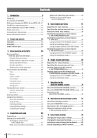 6
6 -
 7
7 -
8
-
9
-
10
-
11
-
12
-
13
-
14
-
15
-
16
-
17
-
18
-
19
-
20
-
21
-
22
-
23
-
24
-
25
-
26
-
27
-
28
-
29
-
30
-
31
-
32
-
33
-
34
-
35
-
36
-
37
-
38
-
39
-
40
-
41
-
42
-
43
-
44
-
45
-
46
-
47
-
48
-
49
-
50
-
51
-
52
-
53
-
54
-
55
-
56
-
57
-
58
-
59
-
60
-
61
-
62
-
63
-
64
-
65
-
66
-
67
-
68
-
69
-
70
-
71
-
72
-
73
-
74
-
75
-
76
-
77
-
78
-
79
-
80
-
81
-
82
-
83
-
84
-
85
-
86
-
87
-
88
-
89
-
90
-
91
-
92
-
93
-
94
-
95
-
96
-
97
-
98
-
99
-
100
-
101
-
102
-
103
-
104
-
105
-
106
-
107
-
108
-
109
-
110
-
111
-
112
-
113
-
114
-
115
-
116
-
117
-
118
-
119
-
120
-
121
-
122
-
123
-
124
-
125
-
126
-
127
-
128
-
129
-
130
-
131
-
132
-
133
-
134
-
135
-
136
-
137
-
138
-
139
-
140
-
141
-
142
-
143
-
144
-
145
-
146
-
147
-
148
-
149
-
150
-
151
-
152
-
153
-
154
-
155
-
156
-
157
-
158
-
159
-
160
-
161
-
162
-
163
-
164
-
165
-
166
-
167
-
168
-
169
-
170
-
171
-
172
-
173
-
174
-
175
-
176
-
177
-
178
-
179
-
180
-
181
-
182
-
183
-
184
-
185
-
186
-
187
-
188
-
189
-
190
-
191
-
192
-
193
-
194
-
195
-
196
-
197
-
198
-
199
-
200
-
201
-
202
-
203
-
204
-
205
-
206
-
207
-
208
-
209
-
210
-
211
-
212
-
213
-
214
-
215
-
216
-
217
-
218
-
219
-
220
-
221
-
222
-
223
-
224
-
225
-
226
-
227
-
228
-
229
-
230
-
231
-
232
-
233
-
234
-
235
-
236
-
237
-
238
-
239
-
240
-
241
-
242
-
243
-
244
-
245
-
246
-
247
-
248
-
249
-
250
-
251
-
252
-
253
-
254
-
255
-
256
-
257
-
258
-
259
-
260
-
261
-
262
-
263
-
264
-
265
-
266
-
267
-
268
-
269
-
270
-
271
-
272
-
273
-
274
-
275
-
276
-
277
-
278
-
279
-
280
-
281
-
282
 |
 |

EN
Owner’s Manual