Yamaha M7CL M7cl V1 Owner's Manual - Page 210
Using cascade connections, Operations on the cascade slave M7CL, Operations on the cascade, slave M7CL
 |
View all Yamaha M7CL manuals
Add to My Manuals
Save this manual to your list of manuals |
Page 210 highlights
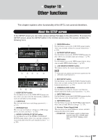
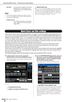
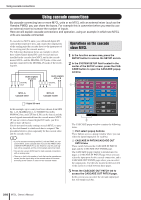
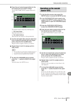
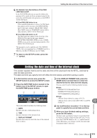
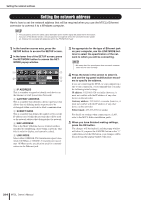
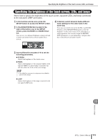
Using cascade connections Using cascade connections By cascade-connecting two or more M7CL units or an M7CL with an external mixer (such as the Yamaha PM5D) you can share the buses. For example this is convenient when you want to use an external mixer to increase the number of inputs. Here we will explain cascade connections and operation, using an example in which two M7CL units are cascade-connected. To cascade two M7CL units, you will install digital I/O cards in their respective slots, and connect the output ports of the sending unit (the cascade slave) to the input ports of the receiving unit (the cascade master). The following illustration shows an example in which three eight-channel digital I/O cards for each unit are installed in the cascade slave M7CL and in the cascade master M7CL, and the DIGITAL OUT jacks of the sending unit connected to the DIGITAL IN jacks of the receiving unit. Audio signals of unit A DIGITAL OUT Audio signals of A + B DIGITAL IN Operations on the cascade slave M7CL 1 In the function access area, press the SETUP button to access the SETUP screen. 2 In the SYSTEM SETUP field located in the center of the SETUP screen, press the CASCADE button to open the CASCADE popup window. 1 M7CL A Cascade slave M7CL B Cascade master : Digital I/O card In this example, up to twenty four buses chosen from MIX bus 1-16, MATRIX bus 1-8, STEREO bus (L/R), MONO(C) bus, and CUE bus (L/R) can be shared, and the mixed signals transmitted from the cascade master M7CL. (If you use sixteen-channel digital I/O cards, you'll be able to share all buses.) You do not need to make settings on each M7CL to specify the slot/channel to which each bus is assigned. The procedure below is given separately for the cascade slave and the cascade master. HINT • If you're cascade-connecting the M7CL with the PM5D, you can use the M7CL as the cascade slave if you set the PM5D's CASCADE IN PORT SELECT to a slot. However, only the audio signals will be cascaded, and the control signals cannot be linked. • You can also use an AD/DA card to make cascade connections with an analog mixer. • There is no limit to the number of units that can be cascade-connected, but the signal delay at the cascade slave will increase according to the number of units from the cascade master. 2 The CASCADE popup window contains the following items. 1 Port select popup buttons These buttons access a popup window where you can select the input/output port for each bus. B CASCADE IN PATCH/CASCADE OUT PATCH tabs These switch between the CASCADE IN PATCH page and the CASCADE OUT PATCH page. The CASCADE popup window is divided into two pages; a CASCADE IN PATCH page where you can select the input ports for the cascade connection, and a CASCADE OUT PATCH page where you can select the output ports. Use the tabs located in the lower left of the screen to switch between these pages. 3 Press the CASCADE OUT PATCH tab to access the CASCADE OUT PATCH page. In this screen you can select the slot and output port that will output each bus. 210 M7CL Owner's Manual
-
 1
1 -
2
-
3
-
4
-
5
-
6
-
7
-
8
-
9
-
10
-
11
-
12
-
13
-
14
-
15
-
16
-
17
-
18
-
19
-
20
-
21
-
22
-
23
-
24
-
25
-
26
-
27
-
28
-
29
-
30
-
31
-
32
-
33
-
34
-
35
-
36
-
37
-
38
-
39
-
40
-
41
-
42
-
43
-
44
-
45
-
46
-
47
-
48
-
49
-
50
-
51
-
52
-
53
-
54
-
55
-
56
-
57
-
58
-
59
-
60
-
61
-
62
-
63
-
64
-
65
-
66
-
67
-
68
-
69
-
70
-
71
-
72
-
73
-
74
-
75
-
76
-
77
-
78
-
79
-
80
-
81
-
82
-
83
-
84
-
85
-
86
-
87
-
88
-
89
-
90
-
91
-
92
-
93
-
94
-
95
-
96
-
97
-
98
-
99
-
100
-
101
-
102
-
103
-
104
-
105
-
106
-
107
-
108
-
109
-
110
-
111
-
112
-
113
-
114
-
115
-
116
-
117
-
118
-
119
-
120
-
121
-
122
-
123
-
124
-
125
-
126
-
127
-
128
-
129
-
130
-
131
-
132
-
133
-
134
-
135
-
136
-
137
-
138
-
139
-
140
-
141
-
142
-
143
-
144
-
145
-
146
-
147
-
148
-
149
-
150
-
151
-
152
-
153
-
154
-
155
-
156
-
157
-
158
-
159
-
160
-
161
-
162
-
163
-
164
-
165
-
166
-
167
-
168
-
169
-
170
-
171
-
172
-
173
-
174
-
175
-
176
-
177
-
178
-
179
-
180
-
181
-
182
-
183
-
184
-
185
-
186
-
187
-
188
-
189
-
190
-
191
-
192
-
193
-
194
-
195
-
196
-
197
-
198
-
199
-
200
-
201
-
202
-
203
-
204
-
 205
205 -
 206
206 -
 207
207 -
 208
208 -
 209
209 -
 210
210 -
 211
211 -
 212
212 -
 213
213 -
 214
214 -
 215
215 -
216
-
217
-
218
-
219
-
220
-
221
-
222
-
223
-
224
-
225
-
226
-
227
-
228
-
229
-
230
-
231
-
232
-
233
-
234
-
235
-
236
-
237
-
238
-
239
-
240
-
241
-
242
-
243
-
244
-
245
-
246
-
247
-
248
-
249
-
250
-
251
-
252
-
253
-
254
-
255
-
256
-
257
-
258
-
259
-
260
-
261
-
262
-
263
-
264
-
265
-
266
-
267
-
268
-
269
-
270
-
271
-
272
-
273
-
274
-
275
-
276
-
277
-
278
-
279
-
280
-
281
-
282
 |
 |