Yamaha M7CL M7cl V1 Owner's Manual - Page 212
Basic settings for MIX buses and MATRIX buses, Use the MIX BUS SETUP/MATRIX BUS
 |
View all Yamaha M7CL manuals
Add to My Manuals
Save this manual to your list of manuals |
Page 212 highlights
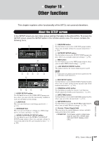
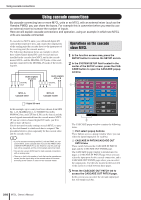
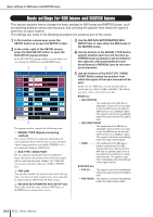
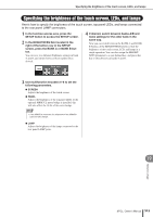
Basic settings for MIX buses and MATRIX buses Basic settings for MIX buses and MATRIX buses This section explains how to change the basic settings for MIX buses and MATRIX buses, such as switching between stereo and monaural, and selecting the position from which the signal is sent from an input channel. The settings you make in the following procedure are saved as part of the scene. 1 In the function access area, press the SETUP button to access the SETUP screen. 2 In the center right of the SETUP screen, press the BUS SETUP button to open the BUS SETUP popup window. In the BUS SETUP popup window you can make various settings for MIX buses and MATRIX buses. 1 2 3 3 Use the MIX BUS SETUP/MATRIX BUS SETUP tabs to view either the MIX buses or the MATRIX buses. 4 Use the buttons in the SIGNAL TYPE field to specify whether each bus will function as STEREO (main parameters will be linked for two adjacent odd-numbered/even-numbered buses) or MONOx2 (use as two monaural channels). 4 This popup window contains the following items. 1 SIGNAL TYPE (Signal processing method) This selects whether two adjacent odd-numbered/ even-numbered buses will be used as stereo channels whose main parameters are linked (STEREO) or as two monaural channels (MONO x2). B BUS TYPE / SEND POINT For two adjacent odd-numbered/even-numbered buses, this selects the position from which the signal will be sent from the input channel. For a MIX bus, you can also switch the bus type (VARI or FIXED) here. C PAN LINK This specifies whether the position from which the signal is sent from an input channel to the stereo bus will be linked with the INPUT TO ST PAN setting. D MIX BUS SETUP/MATRIX BUS SETUP tabs These tabs switch the type of buses (MIX buses or MATRIX buses) shown in the screen. 5 Use the buttons of the BUS TYPE / SEND POINT field to select the position from which the signal of the input channel will be sent. In the case of a MIX bus, you can use this field to switch the type of bus (VARI or FIXED). The following items can be selected for each bus. ● MIX bus • VARI [PRE EQ] ........... The send level of the MIX bus is adjustable. Choose this if you want to use the MIX bus as an external effect send or as a foldback output. The signal is sent from immediately before the input channel EQ (attenuator). • VARI [PRE FADER] ........... The send level of the MIX bus is adjustable. Choose this if you want to use the MIX bus as an external effect send or as a foldback output. The signal is sent from immediately before the input channel fader. • FIXED The send level of the MIX bus is fixed at nominal level (0.0 dB). Choose this if you want to use the MIX bus as a group output or as a bus output for recording on a multitrack recorder. The signal is sent from immediately after the [ON] key of the input channel. ● MATRIX bus • PRE EQ.......... The signal is sent from immediately before the input channel EQ (attenuator). • PRE FADER ... The signal is sent from immediately before the input channel fader. 212 M7CL Owner's Manual
-
 1
1 -
2
-
3
-
4
-
5
-
6
-
7
-
8
-
9
-
10
-
11
-
12
-
13
-
14
-
15
-
16
-
17
-
18
-
19
-
20
-
21
-
22
-
23
-
24
-
25
-
26
-
27
-
28
-
29
-
30
-
31
-
32
-
33
-
34
-
35
-
36
-
37
-
38
-
39
-
40
-
41
-
42
-
43
-
44
-
45
-
46
-
47
-
48
-
49
-
50
-
51
-
52
-
53
-
54
-
55
-
56
-
57
-
58
-
59
-
60
-
61
-
62
-
63
-
64
-
65
-
66
-
67
-
68
-
69
-
70
-
71
-
72
-
73
-
74
-
75
-
76
-
77
-
78
-
79
-
80
-
81
-
82
-
83
-
84
-
85
-
86
-
87
-
88
-
89
-
90
-
91
-
92
-
93
-
94
-
95
-
96
-
97
-
98
-
99
-
100
-
101
-
102
-
103
-
104
-
105
-
106
-
107
-
108
-
109
-
110
-
111
-
112
-
113
-
114
-
115
-
116
-
117
-
118
-
119
-
120
-
121
-
122
-
123
-
124
-
125
-
126
-
127
-
128
-
129
-
130
-
131
-
132
-
133
-
134
-
135
-
136
-
137
-
138
-
139
-
140
-
141
-
142
-
143
-
144
-
145
-
146
-
147
-
148
-
149
-
150
-
151
-
152
-
153
-
154
-
155
-
156
-
157
-
158
-
159
-
160
-
161
-
162
-
163
-
164
-
165
-
166
-
167
-
168
-
169
-
170
-
171
-
172
-
173
-
174
-
175
-
176
-
177
-
178
-
179
-
180
-
181
-
182
-
183
-
184
-
185
-
186
-
187
-
188
-
189
-
190
-
191
-
192
-
193
-
194
-
195
-
196
-
197
-
198
-
199
-
200
-
201
-
202
-
203
-
204
-
205
-
206
-
 207
207 -
 208
208 -
 209
209 -
 210
210 -
 211
211 -
 212
212 -
 213
213 -
 214
214 -
 215
215 -
 216
216 -
 217
217 -
218
-
219
-
220
-
221
-
222
-
223
-
224
-
225
-
226
-
227
-
228
-
229
-
230
-
231
-
232
-
233
-
234
-
235
-
236
-
237
-
238
-
239
-
240
-
241
-
242
-
243
-
244
-
245
-
246
-
247
-
248
-
249
-
250
-
251
-
252
-
253
-
254
-
255
-
256
-
257
-
258
-
259
-
260
-
261
-
262
-
263
-
264
-
265
-
266
-
267
-
268
-
269
-
270
-
271
-
272
-
273
-
274
-
275
-
276
-
277
-
278
-
279
-
280
-
281
-
282
 |
 |
