Yamaha M7CL M7cl V1 Owner's Manual - Page 214
Setting the network address, IP ADDRESS - editor mac
 |
View all Yamaha M7CL manuals
Add to My Manuals
Save this manual to your list of manuals |
Page 214 highlights
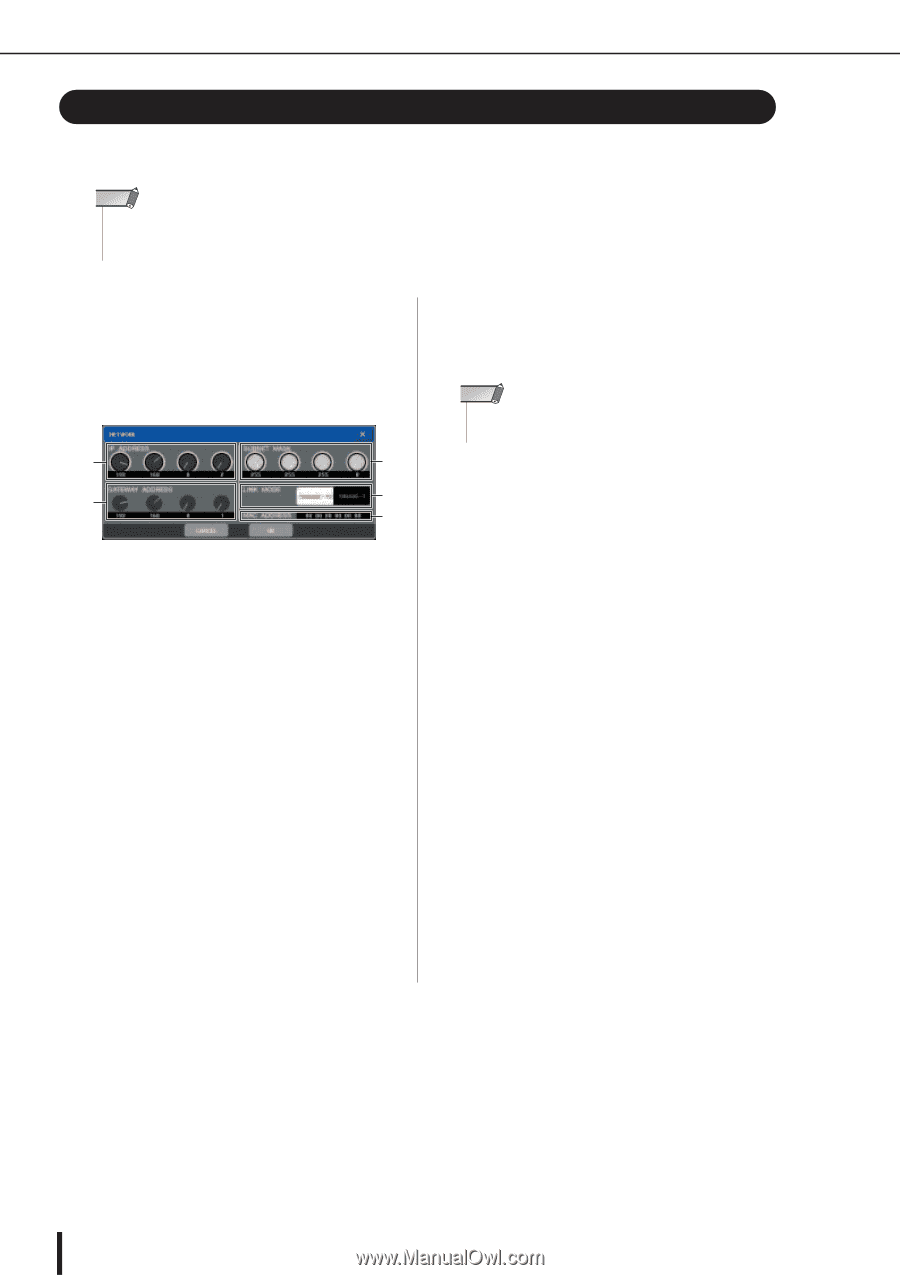
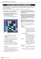
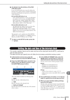
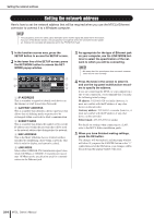
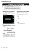
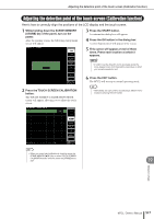
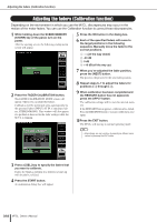
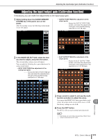
Setting the network address Setting the network address Here's how to set the network address that will be required when you use the M7CL's Ethernet connector to connect it to a Windows computer. NOTE • The cue signal is sent to the same output destination as the monitor signal. Be aware that for this reason, if you turn off the Monitor function, the cue signal will no longer be sent to the connected monitor speakers. However, the cue signal will always be sent to the PHONES OUT jack. 1 In the function access area, press the SETUP button to access the SETUP screen. 2 In the lower line of the SETUP screen, press the NETWORK button to access the NETWORK popup window. 1 3 2 5 4 1 IP ADDRESS This is a number assigned to identify each device on the Internet or LAN (Local Area Network). B GATEWAY ADDRESS This is a number that identifies a device (gateway) that allows data of differing media or protocol to be exchanged within a network to allow communication. C SUBNET MASK This is a number that defines the number of bits (of the IP address used within the network) that will be used as the network address that distinguishes the network. D MAC ADDRESS This is the MAC (Machine Access Control) address specified for identifying a host within a network. This field is only for display, and cannot be edited. E LINK MODE Select either 100BASE-TX (transmission speed: maximum 100 Mbps) or 10BASE-T (transmission speed: max 10 Mbps) as the specification used for communication via the Ethernet jack. 3 As appropriate for the type of Ethernet jack on your computer, use the LINK MODE buttons to select the specification of the network to which you will be connecting. NOTE • Be aware that if the specification does not match, communication will not occur correctly. 4 Press the knob in the screen to select it, and use the top panel multifunction encoders to specify the address. If you are connecting the M7CL to your computer in a one-to-one connection, we recommend that you make the following initial settings. IP address: 192.168.0.128 or similar (however, it must not conflict with the IP address of any other device on the network) Gateway address: 192.168.0.1 or similar (however, it must not conflict with the IP address of any other device on the network) Subnet mask: 255.255.255.0 or similar For details on settings when connecting to a LAN, refer to the M7CL Editor installation guide. 5 When you have finished making settings, press the OK button. The changes will be finalized, and the popup window will close. If you press the CANCEL button or the "×" symbol instead of the OK button, your changes will be discarded and the popup window will close. 214 M7CL Owner's Manual
-
 1
1 -
2
-
3
-
4
-
5
-
6
-
7
-
8
-
9
-
10
-
11
-
12
-
13
-
14
-
15
-
16
-
17
-
18
-
19
-
20
-
21
-
22
-
23
-
24
-
25
-
26
-
27
-
28
-
29
-
30
-
31
-
32
-
33
-
34
-
35
-
36
-
37
-
38
-
39
-
40
-
41
-
42
-
43
-
44
-
45
-
46
-
47
-
48
-
49
-
50
-
51
-
52
-
53
-
54
-
55
-
56
-
57
-
58
-
59
-
60
-
61
-
62
-
63
-
64
-
65
-
66
-
67
-
68
-
69
-
70
-
71
-
72
-
73
-
74
-
75
-
76
-
77
-
78
-
79
-
80
-
81
-
82
-
83
-
84
-
85
-
86
-
87
-
88
-
89
-
90
-
91
-
92
-
93
-
94
-
95
-
96
-
97
-
98
-
99
-
100
-
101
-
102
-
103
-
104
-
105
-
106
-
107
-
108
-
109
-
110
-
111
-
112
-
113
-
114
-
115
-
116
-
117
-
118
-
119
-
120
-
121
-
122
-
123
-
124
-
125
-
126
-
127
-
128
-
129
-
130
-
131
-
132
-
133
-
134
-
135
-
136
-
137
-
138
-
139
-
140
-
141
-
142
-
143
-
144
-
145
-
146
-
147
-
148
-
149
-
150
-
151
-
152
-
153
-
154
-
155
-
156
-
157
-
158
-
159
-
160
-
161
-
162
-
163
-
164
-
165
-
166
-
167
-
168
-
169
-
170
-
171
-
172
-
173
-
174
-
175
-
176
-
177
-
178
-
179
-
180
-
181
-
182
-
183
-
184
-
185
-
186
-
187
-
188
-
189
-
190
-
191
-
192
-
193
-
194
-
195
-
196
-
197
-
198
-
199
-
200
-
201
-
202
-
203
-
204
-
205
-
206
-
207
-
208
-
 209
209 -
 210
210 -
 211
211 -
 212
212 -
 213
213 -
 214
214 -
 215
215 -
 216
216 -
 217
217 -
 218
218 -
 219
219 -
220
-
221
-
222
-
223
-
224
-
225
-
226
-
227
-
228
-
229
-
230
-
231
-
232
-
233
-
234
-
235
-
236
-
237
-
238
-
239
-
240
-
241
-
242
-
243
-
244
-
245
-
246
-
247
-
248
-
249
-
250
-
251
-
252
-
253
-
254
-
255
-
256
-
257
-
258
-
259
-
260
-
261
-
262
-
263
-
264
-
265
-
266
-
267
-
268
-
269
-
270
-
271
-
272
-
273
-
274
-
275
-
276
-
277
-
278
-
279
-
280
-
281
-
282
 |
 |