Yamaha M7CL M7cl V1 Owner's Manual - Page 23
WORD CLOCK IN/OUT connectors, MIDI IN/OUT connectors, ETHERNET connector, Slots 1-3, AC IN connector - cards
 |
View all Yamaha M7CL manuals
Add to My Manuals
Save this manual to your list of manuals |
Page 23 highlights
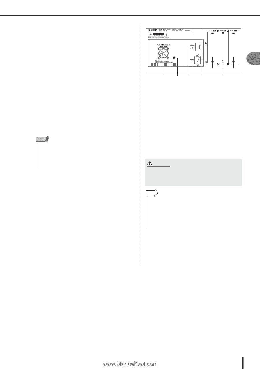
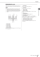
Rear panel G WORD CLOCK IN/OUT connectors These are BNC connectors used to transmit/receive word clock signals to/from an external device. The WORD CLOCK IN connector is internally terminated by 75 ohms. H MIDI IN/OUT connectors These connectors are used to transmit and receive MIDI messages to and from external MIDI devices. The MIDI IN connector receives messages from an external device, and the MIDI OUT connector transmits messages from the M7CL. These are used mainly to record M7CL parameter operations or scene/library selections on an external device, or to control M7CL parameters from an external device. I ETHERNET connector This connector allows the M7CL to be connected via a CAT3 (transmission speed up to 10 Mbps) or CAT5 (transmission speed up to 100 Mbps) Ethernet cable to a Windows computer. This is used mainly to control mix parameters or edit scene memories and libraries from the dedicated "M7CL Editor" application program. NOTE • The DME Network Driver required for connection to the Ethernet connector, the Studio Manager required for starting up M7CL Editor, and the M7CL Editor itself can be downloaded from the following Yamaha website. http://www.yamahaproaudio.com/ 2 Panels and controls M NL K J J Slots 1-3 These slots allow separately sold mini-YGDAI I/O cards to be installed to expand the input/output ports. K AC IN connector Connect the included power cable to this connector. L POWER switch This switch turns the internal power supply on/off. M DC POWER INPUT connector You can connect the separately sold PW800W power supply here as a backup external power supply. If the PW800W is connected, the M7CL will continue receiving power from the PW800W even if its own internal power supply shuts down due to a problem. CAUTION • If you connect the PW800W, you must be sure to first poweroff both the M7CL and the PW800W. Then use the optional power supply cable (PSL360) to make the connection. Failure to observe this will cause malfunctions or electric shock. HINT • If the PW800W is connected, the M7CL will operate correctly whether its own internal power supply and the PW800W are both turned on, or whether just one of these is turned on. • If both power supplies are on, and an abnormality is detected in one of the power supplies, the M7CL will automatically switch to the other power supply. If this occurs, the touch screen will show a message to indicate this. N Grounding screw In order to ensure safe operation, use this screw to connect the M7CL to an electrical ground. Making a correct ground connection will effectively eliminate noise such as hum and interference. M7CL Owner's Manual 23
-
 1
1 -
2
-
3
-
4
-
5
-
6
-
7
-
8
-
9
-
10
-
11
-
12
-
13
-
14
-
15
-
16
-
17
-
 18
18 -
 19
19 -
 20
20 -
 21
21 -
 22
22 -
 23
23 -
 24
24 -
 25
25 -
 26
26 -
 27
27 -
 28
28 -
29
-
30
-
31
-
32
-
33
-
34
-
35
-
36
-
37
-
38
-
39
-
40
-
41
-
42
-
43
-
44
-
45
-
46
-
47
-
48
-
49
-
50
-
51
-
52
-
53
-
54
-
55
-
56
-
57
-
58
-
59
-
60
-
61
-
62
-
63
-
64
-
65
-
66
-
67
-
68
-
69
-
70
-
71
-
72
-
73
-
74
-
75
-
76
-
77
-
78
-
79
-
80
-
81
-
82
-
83
-
84
-
85
-
86
-
87
-
88
-
89
-
90
-
91
-
92
-
93
-
94
-
95
-
96
-
97
-
98
-
99
-
100
-
101
-
102
-
103
-
104
-
105
-
106
-
107
-
108
-
109
-
110
-
111
-
112
-
113
-
114
-
115
-
116
-
117
-
118
-
119
-
120
-
121
-
122
-
123
-
124
-
125
-
126
-
127
-
128
-
129
-
130
-
131
-
132
-
133
-
134
-
135
-
136
-
137
-
138
-
139
-
140
-
141
-
142
-
143
-
144
-
145
-
146
-
147
-
148
-
149
-
150
-
151
-
152
-
153
-
154
-
155
-
156
-
157
-
158
-
159
-
160
-
161
-
162
-
163
-
164
-
165
-
166
-
167
-
168
-
169
-
170
-
171
-
172
-
173
-
174
-
175
-
176
-
177
-
178
-
179
-
180
-
181
-
182
-
183
-
184
-
185
-
186
-
187
-
188
-
189
-
190
-
191
-
192
-
193
-
194
-
195
-
196
-
197
-
198
-
199
-
200
-
201
-
202
-
203
-
204
-
205
-
206
-
207
-
208
-
209
-
210
-
211
-
212
-
213
-
214
-
215
-
216
-
217
-
218
-
219
-
220
-
221
-
222
-
223
-
224
-
225
-
226
-
227
-
228
-
229
-
230
-
231
-
232
-
233
-
234
-
235
-
236
-
237
-
238
-
239
-
240
-
241
-
242
-
243
-
244
-
245
-
246
-
247
-
248
-
249
-
250
-
251
-
252
-
253
-
254
-
255
-
256
-
257
-
258
-
259
-
260
-
261
-
262
-
263
-
264
-
265
-
266
-
267
-
268
-
269
-
270
-
271
-
272
-
273
-
274
-
275
-
276
-
277
-
278
-
279
-
280
-
281
-
282
 |
 |