HP 6125G HP 6125G & 6125G/XG Blade Switches Layer 2 - LAN Switching Co - Page 103
Enabling BPDU tunneling, Configuration prerequisites
 |
View all HP 6125G manuals
Add to My Manuals
Save this manual to your list of manuals |
Page 103 highlights
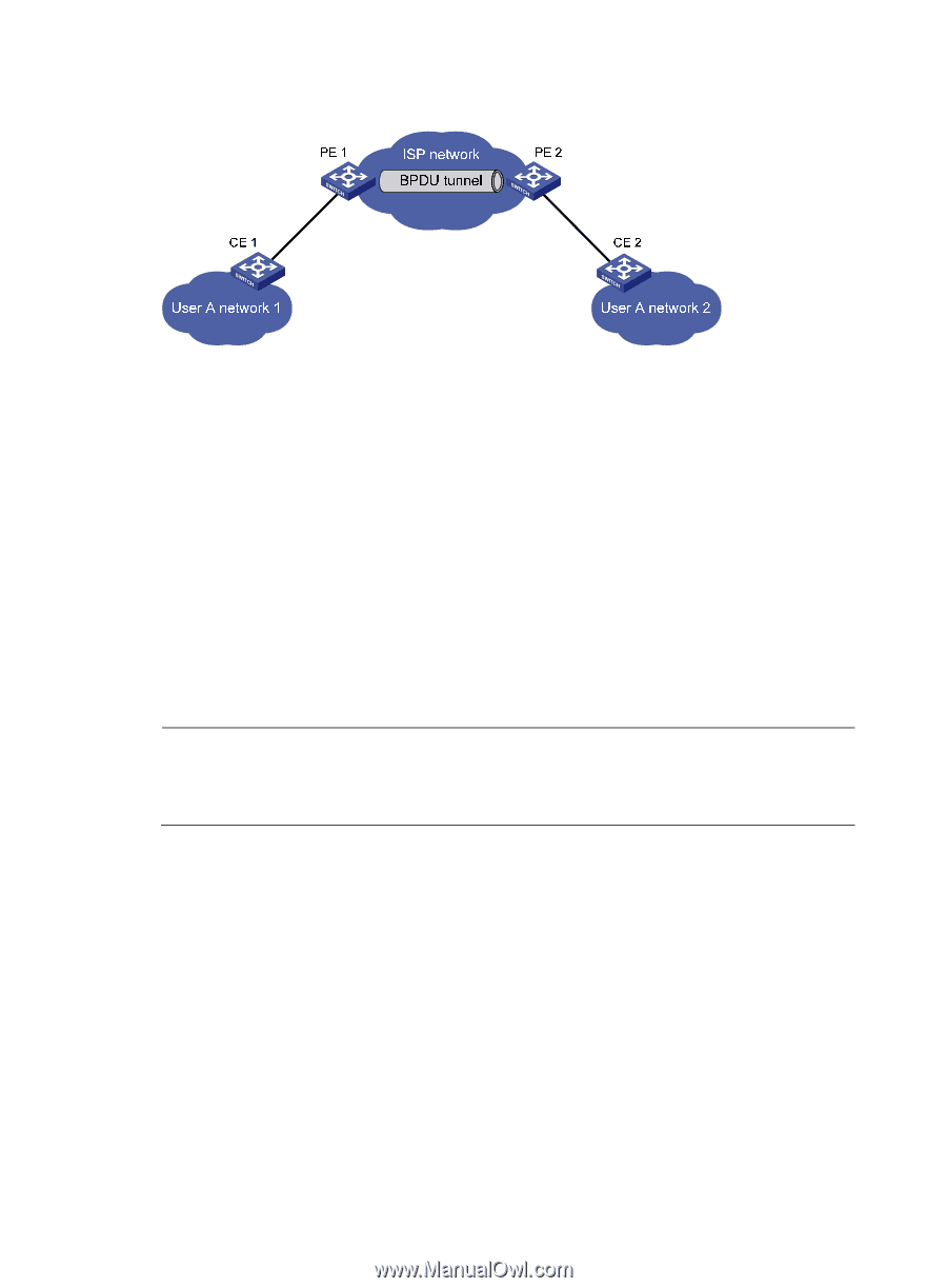
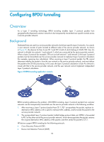
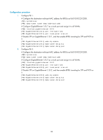
Figure 26 BPDU tunneling implementation The upper section of Figure 26 represents the service provider network (ISP network). The lower section, including User A network 1 and User A network 2, represents the customer networks. Enabling BPDU tunneling on edge devices (PE 1 and PE 2) in the service provider network allows BPDUs of User A network 1 and User A network 2 to be transparently transmitted through the service provider network. This ensures consistent spanning tree calculation throughout User A network, without affecting the spanning tree calculation of the service provider network. Assume that a BPDU is sent from User A network 1 to User A network 2. The BPDU is sent by using the following workflow: 1. At the ingress of the service provider network, PE 1 changes the destination MAC address of the BPDU from 0x0180-C200-0000 to a special multicast MAC address, 0x010F-E200-0003 (the default multicast MAC address), for example. In the service provider network, the modified BPDU is forwarded as a data packet in the VLAN assigned to User A. 2. At the egress of the service provider network, PE 2 recognizes the BPDU with the destination MAC address 0x010F-E200-0003, restores its original destination MAC address 0x0180-C200-0000, and then sends the BPDU to CE 2. NOTE: Through configuration, make sure that the VLAN tags carried in BPDUs are neither changed nor removed during the transparent transmission in the service provider network. Otherwise, the devices in the service provider network will fail to transparently transmit the customer network BPDUs correctly. Enabling BPDU tunneling Configuration prerequisites Before configuring BPDU tunneling for a protocol, perform the following tasks: • Enable the protocol in the customer network. • Assign the port on which you want to enable BPDU tunneling on the PE device and the connected port on the CE device to the same VLAN. • Configure ports that connect network devices in the service provider network as trunk ports that allow packets of any VLAN to pass through. 94
-
 1
1 -
2
-
3
-
4
-
5
-
6
-
7
-
8
-
9
-
10
-
11
-
12
-
13
-
14
-
15
-
16
-
17
-
18
-
19
-
20
-
21
-
22
-
23
-
24
-
25
-
26
-
27
-
28
-
29
-
30
-
31
-
32
-
33
-
34
-
35
-
36
-
37
-
38
-
39
-
40
-
41
-
42
-
43
-
44
-
45
-
46
-
47
-
48
-
49
-
50
-
51
-
52
-
53
-
54
-
55
-
56
-
57
-
58
-
59
-
60
-
61
-
62
-
63
-
64
-
65
-
66
-
67
-
68
-
69
-
70
-
71
-
72
-
73
-
74
-
75
-
76
-
77
-
78
-
79
-
80
-
81
-
82
-
83
-
84
-
85
-
86
-
87
-
88
-
89
-
90
-
91
-
92
-
93
-
94
-
95
-
96
-
97
-
 98
98 -
 99
99 -
 100
100 -
 101
101 -
 102
102 -
 103
103 -
 104
104 -
 105
105 -
 106
106 -
 107
107 -
 108
108 -
109
-
110
-
111
-
112
-
113
-
114
-
115
-
116
-
117
-
118
-
119
-
120
-
121
-
122
-
123
-
124
-
125
-
126
-
127
-
128
-
129
-
130
-
131
-
132
-
133
-
134
-
135
-
136
-
137
-
138
-
139
-
140
-
141
-
142
-
143
-
144
-
145
-
146
-
147
-
148
-
149
-
150
-
151
-
152
-
153
-
154
-
155
-
156
-
157
-
158
-
159
-
160
-
161
-
162
-
163
-
164
-
165
-
166
-
167
-
168
-
169
-
170
-
171
-
172
-
173
-
174
-
175
-
176
-
177
-
178
-
179
-
180
-
181
-
182
-
183
-
184
-
185
-
186
-
187
-
188
-
189
-
190
-
191
-
192
-
193
-
194
-
195
-
196
-
197
-
198
-
199
-
200
-
201
-
202
-
203
-
204
-
205
-
206
-
207
-
208
-
209
-
210
-
211
-
212
-
213
-
214
-
215
-
216
-
217
-
218
-
219
-
220
-
221
-
222
-
223
-
224
-
225
-
226
-
227
-
228
-
229
-
230
-
231
 |
 |