HP 6125G HP 6125G & 6125G/XG Blade Switches Layer 2 - LAN Switching Co - Page 19
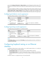
Setting the MDI mode of an Ethernet interface
 |
View all HP 6125G manuals
Add to My Manuals
Save this manual to your list of manuals |
Page 19 highlights
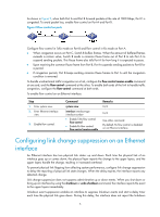
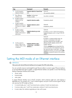
Step Command 3. Set the loopback detection interval. loopback-detection interval-time time 4. Enter Ethernet interface view. interface interface-type interface-number 5. Enable loopback detection on the interface. loopback-detection enable 6. Enable loopback detection control on a loopback-detection control trunk port or a hybrid enable port. 7. Enable loopback detection in all the loopback-detection per-vlan VLANs on the trunk or enable hybrid port. 8. Set the protective action to take on the interface when a loop is detected. loopback-detection action { no-learning | semi-block | shutdown } Remarks Optional. 30 seconds by default. Use either command. Disabled by default. Optional. Disabled by default. Optional. By default, a trunk or hybrid port performs loopback detection only in its port VLAN ID (PVID). Optional. By default, a looped interface does not receive or send packets; the system generates traps and log messages, and deletes all MAC address entries of the looped interface. With the shutdown keyword specified, the switch shuts down the looped ports and set their physical state to Loop down. When a looped port recovers, you must use the undo shutdown command to restore its forwarding capability. Setting the MDI mode of an Ethernet interface IMPORTANT: Fiber ports and internal Ethernet interfaces do not support the MDI mode setting. You can use both crossover and straight-through Ethernet cables to connect copper Ethernet interfaces. To accommodate these types of cables, a copper Ethernet interface can operate in one of the following Medium Dependent Interface (MDI) modes: • Across mode • Normal mode • Auto mode A copper Ethernet interface uses an RJ-45 connector, which comprises eight pins, each playing a dedicated role. For example, pins 1 and 2 transmit signals, and pins 3 and 6 receive signals. The pin role varies by the MDI modes as follows: • In normal mode, pins 1 and 2 are transmit pins, and pins 3 and 6 are receive pins. • In across mode, pins 1 and 2 are receive pins, and pins 3 and 6 are transmit pins. • In auto mode, the interface negotiates pin roles with its peer. 10
-
 1
1 -
2
-
3
-
4
-
5
-
6
-
7
-
8
-
9
-
10
-
11
-
12
-
13
-
 14
14 -
 15
15 -
 16
16 -
 17
17 -
 18
18 -
 19
19 -
 20
20 -
 21
21 -
 22
22 -
 23
23 -
 24
24 -
25
-
26
-
27
-
28
-
29
-
30
-
31
-
32
-
33
-
34
-
35
-
36
-
37
-
38
-
39
-
40
-
41
-
42
-
43
-
44
-
45
-
46
-
47
-
48
-
49
-
50
-
51
-
52
-
53
-
54
-
55
-
56
-
57
-
58
-
59
-
60
-
61
-
62
-
63
-
64
-
65
-
66
-
67
-
68
-
69
-
70
-
71
-
72
-
73
-
74
-
75
-
76
-
77
-
78
-
79
-
80
-
81
-
82
-
83
-
84
-
85
-
86
-
87
-
88
-
89
-
90
-
91
-
92
-
93
-
94
-
95
-
96
-
97
-
98
-
99
-
100
-
101
-
102
-
103
-
104
-
105
-
106
-
107
-
108
-
109
-
110
-
111
-
112
-
113
-
114
-
115
-
116
-
117
-
118
-
119
-
120
-
121
-
122
-
123
-
124
-
125
-
126
-
127
-
128
-
129
-
130
-
131
-
132
-
133
-
134
-
135
-
136
-
137
-
138
-
139
-
140
-
141
-
142
-
143
-
144
-
145
-
146
-
147
-
148
-
149
-
150
-
151
-
152
-
153
-
154
-
155
-
156
-
157
-
158
-
159
-
160
-
161
-
162
-
163
-
164
-
165
-
166
-
167
-
168
-
169
-
170
-
171
-
172
-
173
-
174
-
175
-
176
-
177
-
178
-
179
-
180
-
181
-
182
-
183
-
184
-
185
-
186
-
187
-
188
-
189
-
190
-
191
-
192
-
193
-
194
-
195
-
196
-
197
-
198
-
199
-
200
-
201
-
202
-
203
-
204
-
205
-
206
-
207
-
208
-
209
-
210
-
211
-
212
-
213
-
214
-
215
-
216
-
217
-
218
-
219
-
220
-
221
-
222
-
223
-
224
-
225
-
226
-
227
-
228
-
229
-
230
-
231
 |
 |