HP 6125G HP 6125G & 6125G/XG Blade Switches Layer 2 - LAN Switching Co - Page 111
Configuring basic settings of a VLAN interface, Configuration procedure
 |
View all HP 6125G manuals
Add to My Manuals
Save this manual to your list of manuals |
Page 111 highlights
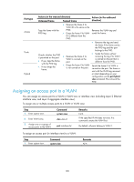
Configuring basic settings of a VLAN interface You can use VLAN interfaces to provide Layer 3 communication between hosts of different VLANs. VLAN interfaces are virtual interfaces used for Layer 3 communication between different VLANs. They do not exist as physical entities on devices. For each VLAN, you can create one VLAN interface. You can assign the VLAN interface an IP address and specify the IP address as the gateway address for the devices in the VLAN, so that traffic can be routed to other IP subnets. Configuration procedure To configure basic settings of a VLAN interface: Step 1. Enter system view. 2. Create a VLAN interface and enter VLAN interface view. Command system-view interface vlan-interface vlan-interface-id 3. Assign an IP address to the ip address ip-address VLAN interface. { mask | mask-length } [ sub ] 4. Configure a description for the VLAN interface. description text 5. Set the MTU for the VLAN interface. mtu size 6. Restore the default settings for the VLAN interface. default 7. Cancel the action of manually shutting down the undo shutdown VLAN interface. Remarks N/A If the VLAN interface already exists, you enter its view directly. Optional. By default, no IP address is assigned to any VLAN interface. Optional. By default, the description of a VLAN is the VLAN interface name. For example, Vlan-interface1 Interface. Optional. By default, the MTU is 1500 bytes. Optional. Optional. By default, a VLAN interface is not manually shut down. The VLAN interface is up if one or more ports in the VLAN is up, and goes down if all ports in the VLAN go down. A VLAN interface shut down with the shutdown command is in the DOWN (Administratively) state until you bring it up, regardless of how the state of the ports in the VLAN changes. NOTE: Before you create a VLAN interface for a VLAN, create the VLAN. VLAN interface configuration example Network requirements As shown in Figure 32, PC A is assigned to VLAN 5. PC B is assigned to VLAN 10. The PCs belong to different IP subnets and cannot communicate with each other. 102
-
 1
1 -
2
-
3
-
4
-
5
-
6
-
7
-
8
-
9
-
10
-
11
-
12
-
13
-
14
-
15
-
16
-
17
-
18
-
19
-
20
-
21
-
22
-
23
-
24
-
25
-
26
-
27
-
28
-
29
-
30
-
31
-
32
-
33
-
34
-
35
-
36
-
37
-
38
-
39
-
40
-
41
-
42
-
43
-
44
-
45
-
46
-
47
-
48
-
49
-
50
-
51
-
52
-
53
-
54
-
55
-
56
-
57
-
58
-
59
-
60
-
61
-
62
-
63
-
64
-
65
-
66
-
67
-
68
-
69
-
70
-
71
-
72
-
73
-
74
-
75
-
76
-
77
-
78
-
79
-
80
-
81
-
82
-
83
-
84
-
85
-
86
-
87
-
88
-
89
-
90
-
91
-
92
-
93
-
94
-
95
-
96
-
97
-
98
-
99
-
100
-
101
-
102
-
103
-
104
-
105
-
 106
106 -
 107
107 -
 108
108 -
 109
109 -
 110
110 -
 111
111 -
 112
112 -
 113
113 -
 114
114 -
 115
115 -
 116
116 -
117
-
118
-
119
-
120
-
121
-
122
-
123
-
124
-
125
-
126
-
127
-
128
-
129
-
130
-
131
-
132
-
133
-
134
-
135
-
136
-
137
-
138
-
139
-
140
-
141
-
142
-
143
-
144
-
145
-
146
-
147
-
148
-
149
-
150
-
151
-
152
-
153
-
154
-
155
-
156
-
157
-
158
-
159
-
160
-
161
-
162
-
163
-
164
-
165
-
166
-
167
-
168
-
169
-
170
-
171
-
172
-
173
-
174
-
175
-
176
-
177
-
178
-
179
-
180
-
181
-
182
-
183
-
184
-
185
-
186
-
187
-
188
-
189
-
190
-
191
-
192
-
193
-
194
-
195
-
196
-
197
-
198
-
199
-
200
-
201
-
202
-
203
-
204
-
205
-
206
-
207
-
208
-
209
-
210
-
211
-
212
-
213
-
214
-
215
-
216
-
217
-
218
-
219
-
220
-
221
-
222
-
223
-
224
-
225
-
226
-
227
-
228
-
229
-
230
-
231
 |
 |