HP 6125G HP 6125G & 6125G/XG Blade Switches Layer 2 - LAN Switching Co - Page 105
BPDU tunneling configuration examples, Network requirements, Configuration procedure
 |
View all HP 6125G manuals
Add to My Manuals
Save this manual to your list of manuals |
Page 105 highlights
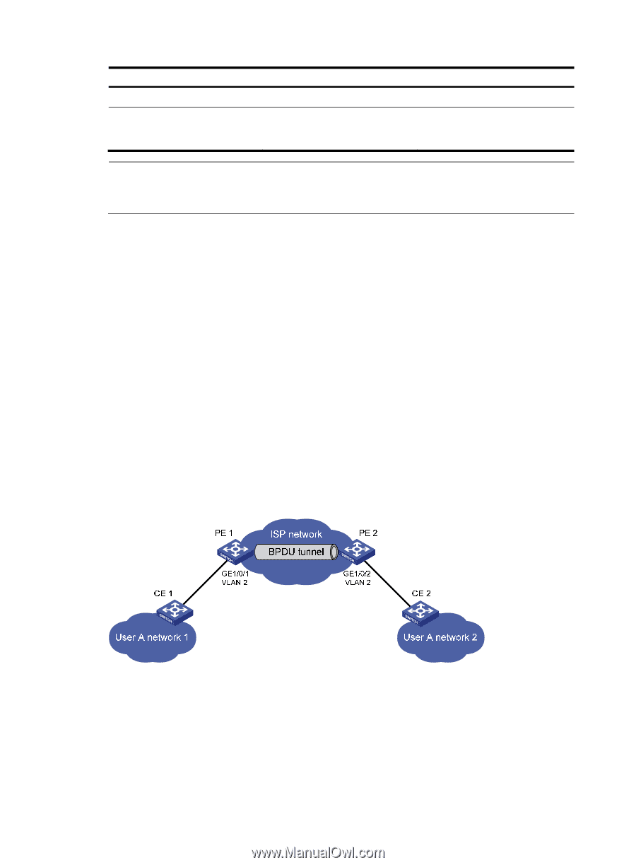
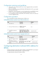
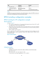
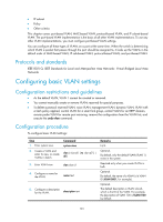
Step 1. Enter system view. 2. Configure the destination multicast MAC address for BPDUs. Command system-view bpdu-tunnel tunnel-dmac mac-address Remarks N/A Optional. 0x010F-E200-0003 by default. NOTE: For BPDUs to be recognized, the destination multicast MAC addresses configured for BPDU tunneling must be the same on the edge devices on the service provider network. BPDU tunneling configuration examples BPDU tunneling for STP configuration example Network requirements As shown in Figure 27: • CE 1 and CE 2 are edges devices on the geographically dispersed network of User A; PE 1 and PE 2 are edge devices on the service provider network. • All ports that connect service provider devices and customer devices are access ports and belong to VLAN 2. All ports that interconnect service provider devices are trunk ports and allow packets of any VLAN to pass through. • MSTP is enabled on User A's network. After the configuration, CE 1 and CE 2 must implement consistent spanning tree calculation across the service provider network, and the destination multicast MAC address carried in BPDUs must be 0x0100-0CCD-CDD0. Figure 27 Network diagram Configuration procedure 1. Configure PE 1: # Configure the destination multicast MAC address for BPDUs as 0x0100-0CCD-CDD0. system-view [PE1] bpdu-tunnel tunnel-dmac 0100-0ccd-cdd0 # Create VLAN 2 and assign GigabitEthernet 1/0/1 to VLAN 2. 96
-
 1
1 -
2
-
3
-
4
-
5
-
6
-
7
-
8
-
9
-
10
-
11
-
12
-
13
-
14
-
15
-
16
-
17
-
18
-
19
-
20
-
21
-
22
-
23
-
24
-
25
-
26
-
27
-
28
-
29
-
30
-
31
-
32
-
33
-
34
-
35
-
36
-
37
-
38
-
39
-
40
-
41
-
42
-
43
-
44
-
45
-
46
-
47
-
48
-
49
-
50
-
51
-
52
-
53
-
54
-
55
-
56
-
57
-
58
-
59
-
60
-
61
-
62
-
63
-
64
-
65
-
66
-
67
-
68
-
69
-
70
-
71
-
72
-
73
-
74
-
75
-
76
-
77
-
78
-
79
-
80
-
81
-
82
-
83
-
84
-
85
-
86
-
87
-
88
-
89
-
90
-
91
-
92
-
93
-
94
-
95
-
96
-
97
-
98
-
99
-
 100
100 -
 101
101 -
 102
102 -
 103
103 -
 104
104 -
 105
105 -
 106
106 -
 107
107 -
 108
108 -
 109
109 -
 110
110 -
111
-
112
-
113
-
114
-
115
-
116
-
117
-
118
-
119
-
120
-
121
-
122
-
123
-
124
-
125
-
126
-
127
-
128
-
129
-
130
-
131
-
132
-
133
-
134
-
135
-
136
-
137
-
138
-
139
-
140
-
141
-
142
-
143
-
144
-
145
-
146
-
147
-
148
-
149
-
150
-
151
-
152
-
153
-
154
-
155
-
156
-
157
-
158
-
159
-
160
-
161
-
162
-
163
-
164
-
165
-
166
-
167
-
168
-
169
-
170
-
171
-
172
-
173
-
174
-
175
-
176
-
177
-
178
-
179
-
180
-
181
-
182
-
183
-
184
-
185
-
186
-
187
-
188
-
189
-
190
-
191
-
192
-
193
-
194
-
195
-
196
-
197
-
198
-
199
-
200
-
201
-
202
-
203
-
204
-
205
-
206
-
207
-
208
-
209
-
210
-
211
-
212
-
213
-
214
-
215
-
216
-
217
-
218
-
219
-
220
-
221
-
222
-
223
-
224
-
225
-
226
-
227
-
228
-
229
-
230
-
231
 |
 |