HP 6125G HP 6125G & 6125G/XG Blade Switches Layer 2 - LAN Switching Co - Page 69
Common root bridge, Port roles, A, Device B
 |
View all HP 6125G manuals
Add to My Manuals
Save this manual to your list of manuals |
Page 69 highlights
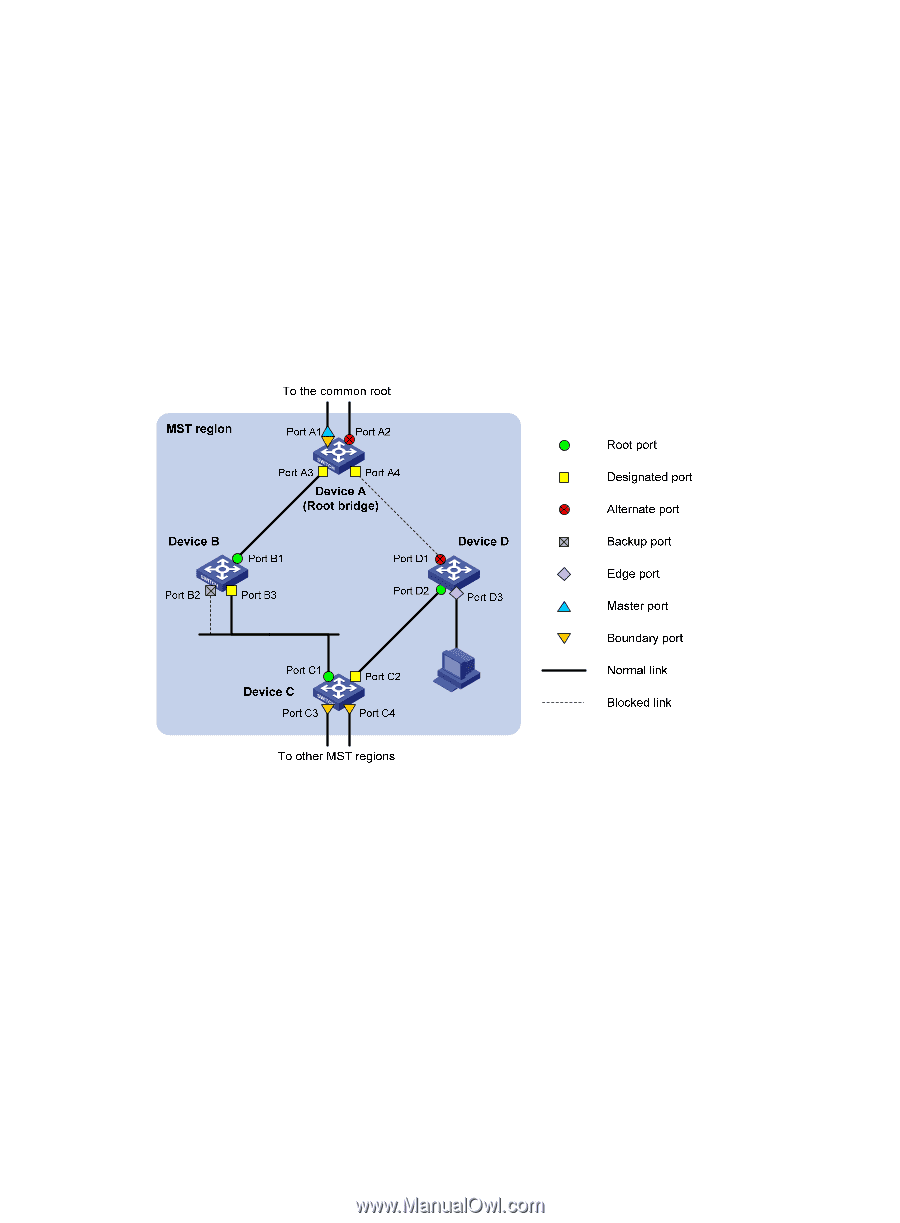
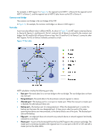
For example, in MST region 3 in Figure 16, the regional root of MSTI 1 is Device B, the regional root of MSTI 2 is Device C, and the regional root of MSTI 0 (also known as the IST) is Device A. Common root bridge The common root bridge is the root bridge of the CIST. In Figure 15, for example, the common root bridge is a device in MST region 1. Port roles A port can play different roles in different MSTIs. As shown in Figure 17, an MST region comprises Device A, Device B, Device C, and Device D. Port A1 and port A2 of Device A connect to the common root bridge. Port B2 and Port B3 of Device B form a loop. Port C3 and Port C4 of Device C connect to other MST regions. Port D3 of Device D directly connects to a host. Figure 17 Port roles MSTP calculation involves the following port roles: • Root port-Forwards data for a non-root bridge to the root bridge. The root bridge does not have any root port. • Designated port-Forwards data to the downstream network segment or device. • Alternate port-The backup port for a root port or master port. When the root port or master port is blocked, the alternate port takes over. • Backup port-The backup port of a designated port. When the designated port is invalid, the backup port becomes the new designated port. A loop occurs when two ports of the same spanning tree device are interconnected, so the device blocks one of the ports. The blocked port acts as the backup. • Edge port-An edge port does not connect to any network device or network segment, but directly connects to a user host. • Master port-A port on the shortest path from the local MST region to the common root bridge. The master port is not always located on the regional root. It is a root port on the IST or CIST and still a master port on the other MSTIs. 60
-
 1
1 -
2
-
3
-
4
-
5
-
6
-
7
-
8
-
9
-
10
-
11
-
12
-
13
-
14
-
15
-
16
-
17
-
18
-
19
-
20
-
21
-
22
-
23
-
24
-
25
-
26
-
27
-
28
-
29
-
30
-
31
-
32
-
33
-
34
-
35
-
36
-
37
-
38
-
39
-
40
-
41
-
42
-
43
-
44
-
45
-
46
-
47
-
48
-
49
-
50
-
51
-
52
-
53
-
54
-
55
-
56
-
57
-
58
-
59
-
60
-
61
-
62
-
63
-
 64
64 -
 65
65 -
 66
66 -
 67
67 -
 68
68 -
 69
69 -
 70
70 -
 71
71 -
 72
72 -
 73
73 -
 74
74 -
75
-
76
-
77
-
78
-
79
-
80
-
81
-
82
-
83
-
84
-
85
-
86
-
87
-
88
-
89
-
90
-
91
-
92
-
93
-
94
-
95
-
96
-
97
-
98
-
99
-
100
-
101
-
102
-
103
-
104
-
105
-
106
-
107
-
108
-
109
-
110
-
111
-
112
-
113
-
114
-
115
-
116
-
117
-
118
-
119
-
120
-
121
-
122
-
123
-
124
-
125
-
126
-
127
-
128
-
129
-
130
-
131
-
132
-
133
-
134
-
135
-
136
-
137
-
138
-
139
-
140
-
141
-
142
-
143
-
144
-
145
-
146
-
147
-
148
-
149
-
150
-
151
-
152
-
153
-
154
-
155
-
156
-
157
-
158
-
159
-
160
-
161
-
162
-
163
-
164
-
165
-
166
-
167
-
168
-
169
-
170
-
171
-
172
-
173
-
174
-
175
-
176
-
177
-
178
-
179
-
180
-
181
-
182
-
183
-
184
-
185
-
186
-
187
-
188
-
189
-
190
-
191
-
192
-
193
-
194
-
195
-
196
-
197
-
198
-
199
-
200
-
201
-
202
-
203
-
204
-
205
-
206
-
207
-
208
-
209
-
210
-
211
-
212
-
213
-
214
-
215
-
216
-
217
-
218
-
219
-
220
-
221
-
222
-
223
-
224
-
225
-
226
-
227
-
228
-
229
-
230
-
231
 |
 |