HP 6125G HP 6125G & 6125G/XG Blade Switches Layer 2 - LAN Switching Co - Page 124
MAC-based VLAN configuration example, Network requirements, Configuration consideration
 |
View all HP 6125G manuals
Add to My Manuals
Save this manual to your list of manuals |
Page 124 highlights
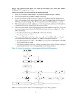
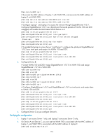
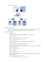
MAC-based VLAN configuration example Network requirements As shown in Figure 35: • GigabitEthernet 1/0/1 of Device A and Device C are each connected to a meeting room. Laptop 1 and Laptop 2 are used for meetings and might be used in either of the two meeting rooms. • Different departments own Laptop 1 and Laptop 2. The two departments use VLAN 100 and VLAN 200, respectively. Each laptop must be able to access only its own department server, no matter which meeting room it is used in. • The MAC address of Laptop 1 is 000D-88F8-4E71, and that of Laptop 2 is 0014-222C-AA69. Figure 35 Network diagram VLAN 100 Server1 IP: 1.1.1.1/24 VLAN 200 Server2 IP: 1.1.2.1/24 GE1/0/13 GE1/0/14 GE1/0/3 GE1/0/4 Device B GE1/0/2 Device A GE1/0/1 VLAN 100 GE1/0/2 Device C GE1/0/1 VLAN 200 Laptop1 IP: 1.1.1.2/24 MAC: 000d-88f8-4e71 Laptop2 IP: 1.1.2.2/24 MAC: 0014-222c-aa69 Configuration consideration • Create VLANs 100 and 200. • Configure the uplink ports of Device A and Device C as trunk ports, and assign them to VLANs 100 and 200. • Configure the downlink ports of Device B as trunk ports, and assign them to VLANs 100 and 200. Assign the uplink ports of Device B to VLANs 100 and 200. • Associate the MAC address of Laptop 1 with VLAN 100, and associate the MAC address of Laptop 2 with VLAN 200. Configuration procedure 1. Configure Device A: # Create VLANs 100 and 200. system-view [DeviceA] vlan 100 [DeviceA-vlan100] quit [DeviceA] vlan 200 115
-
 1
1 -
2
-
3
-
4
-
5
-
6
-
7
-
8
-
9
-
10
-
11
-
12
-
13
-
14
-
15
-
16
-
17
-
18
-
19
-
20
-
21
-
22
-
23
-
24
-
25
-
26
-
27
-
28
-
29
-
30
-
31
-
32
-
33
-
34
-
35
-
36
-
37
-
38
-
39
-
40
-
41
-
42
-
43
-
44
-
45
-
46
-
47
-
48
-
49
-
50
-
51
-
52
-
53
-
54
-
55
-
56
-
57
-
58
-
59
-
60
-
61
-
62
-
63
-
64
-
65
-
66
-
67
-
68
-
69
-
70
-
71
-
72
-
73
-
74
-
75
-
76
-
77
-
78
-
79
-
80
-
81
-
82
-
83
-
84
-
85
-
86
-
87
-
88
-
89
-
90
-
91
-
92
-
93
-
94
-
95
-
96
-
97
-
98
-
99
-
100
-
101
-
102
-
103
-
104
-
105
-
106
-
107
-
108
-
109
-
110
-
111
-
112
-
113
-
114
-
115
-
116
-
117
-
118
-
 119
119 -
 120
120 -
 121
121 -
 122
122 -
 123
123 -
 124
124 -
 125
125 -
 126
126 -
 127
127 -
 128
128 -
 129
129 -
130
-
131
-
132
-
133
-
134
-
135
-
136
-
137
-
138
-
139
-
140
-
141
-
142
-
143
-
144
-
145
-
146
-
147
-
148
-
149
-
150
-
151
-
152
-
153
-
154
-
155
-
156
-
157
-
158
-
159
-
160
-
161
-
162
-
163
-
164
-
165
-
166
-
167
-
168
-
169
-
170
-
171
-
172
-
173
-
174
-
175
-
176
-
177
-
178
-
179
-
180
-
181
-
182
-
183
-
184
-
185
-
186
-
187
-
188
-
189
-
190
-
191
-
192
-
193
-
194
-
195
-
196
-
197
-
198
-
199
-
200
-
201
-
202
-
203
-
204
-
205
-
206
-
207
-
208
-
209
-
210
-
211
-
212
-
213
-
214
-
215
-
216
-
217
-
218
-
219
-
220
-
221
-
222
-
223
-
224
-
225
-
226
-
227
-
228
-
229
-
230
-
231
 |
 |
