HP 6125G HP 6125G & 6125G/XG Blade Switches Layer 2 - LAN Switching Co - Page 98
map VLAN 10, VLAN 30, Con Device C
 |
View all HP 6125G manuals
Add to My Manuals
Save this manual to your list of manuals |
Page 98 highlights
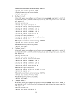
# Specify the current device as the root bridge of MSTI 1. [DeviceA] stp instance 1 root primary # Enable the spanning tree feature globally. [DeviceA] stp enable 3. Configure Device B: # Enter MST region view, configure the MST region name as example, map VLAN 10, VLAN 30, and VLAN 40 to MSTI 1, MSTI 3, and MSTI 4, respectively, and configure the revision level of the MST region as 0. system-view [DeviceB] stp region-configuration [DeviceB-mst-region] region-name example [DeviceB-mst-region] instance 1 vlan 10 [DeviceB-mst-region] instance 3 vlan 30 [DeviceB-mst-region] instance 4 vlan 40 [DeviceB-mst-region] revision-level 0 # Activate MST region configuration. [DeviceB-mst-region] active region-configuration [DeviceB-mst-region] quit # Specify the current device as the root bridge of MSTI 3. [DeviceB] stp instance 3 root primary # Enable the spanning tree feature globally. [DeviceB] stp enable 4. Configure Device C: # Enter MST region view, configure the MST region name as example, map VLAN 10, VLAN 30, and VLAN 40 to MSTI 1, MSTI 3, and MSTI 4, respectively, and configure the revision level of the MST region as 0. system-view [DeviceC] stp region-configuration [DeviceC-mst-region] region-name example [DeviceC-mst-region] instance 1 vlan 10 [DeviceC-mst-region] instance 3 vlan 30 [DeviceC-mst-region] instance 4 vlan 40 [DeviceC-mst-region] revision-level 0 # Activate MST region configuration. [DeviceC-mst-region] active region-configuration [DeviceC-mst-region] quit # Specify the current device as the root bridge of MSTI 4. [DeviceC] stp instance 4 root primary # Enable the spanning tree feature globally. [DeviceC] stp enable 5. Configure Device D: # Enter MST region view, configure the MST region name as example, map VLAN 10, VLAN 30, and VLAN 40 to MSTI 1, MSTI 3, and MSTI 4, respectively, and configure the revision level of the MST region as 0. system-view [DeviceD] stp region-configuration 89
-
 1
1 -
2
-
3
-
4
-
5
-
6
-
7
-
8
-
9
-
10
-
11
-
12
-
13
-
14
-
15
-
16
-
17
-
18
-
19
-
20
-
21
-
22
-
23
-
24
-
25
-
26
-
27
-
28
-
29
-
30
-
31
-
32
-
33
-
34
-
35
-
36
-
37
-
38
-
39
-
40
-
41
-
42
-
43
-
44
-
45
-
46
-
47
-
48
-
49
-
50
-
51
-
52
-
53
-
54
-
55
-
56
-
57
-
58
-
59
-
60
-
61
-
62
-
63
-
64
-
65
-
66
-
67
-
68
-
69
-
70
-
71
-
72
-
73
-
74
-
75
-
76
-
77
-
78
-
79
-
80
-
81
-
82
-
83
-
84
-
85
-
86
-
87
-
88
-
89
-
90
-
91
-
92
-
 93
93 -
 94
94 -
 95
95 -
 96
96 -
 97
97 -
 98
98 -
 99
99 -
 100
100 -
 101
101 -
 102
102 -
 103
103 -
104
-
105
-
106
-
107
-
108
-
109
-
110
-
111
-
112
-
113
-
114
-
115
-
116
-
117
-
118
-
119
-
120
-
121
-
122
-
123
-
124
-
125
-
126
-
127
-
128
-
129
-
130
-
131
-
132
-
133
-
134
-
135
-
136
-
137
-
138
-
139
-
140
-
141
-
142
-
143
-
144
-
145
-
146
-
147
-
148
-
149
-
150
-
151
-
152
-
153
-
154
-
155
-
156
-
157
-
158
-
159
-
160
-
161
-
162
-
163
-
164
-
165
-
166
-
167
-
168
-
169
-
170
-
171
-
172
-
173
-
174
-
175
-
176
-
177
-
178
-
179
-
180
-
181
-
182
-
183
-
184
-
185
-
186
-
187
-
188
-
189
-
190
-
191
-
192
-
193
-
194
-
195
-
196
-
197
-
198
-
199
-
200
-
201
-
202
-
203
-
204
-
205
-
206
-
207
-
208
-
209
-
210
-
211
-
212
-
213
-
214
-
215
-
216
-
217
-
218
-
219
-
220
-
221
-
222
-
223
-
224
-
225
-
226
-
227
-
228
-
229
-
230
-
231
 |
 |