HP 6125G HP 6125G & 6125G/XG Blade Switches Layer 2 - LAN Switching Co - Page 97
Configuration procedure, Create VLAN 20, VLAN 30, and VLAN 40 on Device D.
 |
View all HP 6125G manuals
Add to My Manuals
Save this manual to your list of manuals |
Page 97 highlights
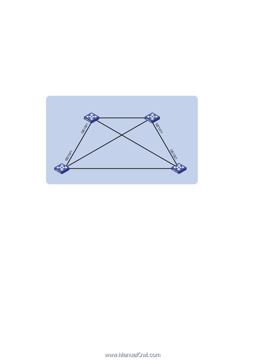
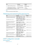
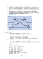
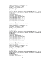
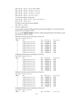
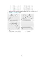
• All devices on the network are in the same MST region. Device A and Device B work at the distribution layer. Device C and Device D work at the access layer. • Configure MSTP so that packets of different VLANs are forwarded along different spanning trees: Packets of VLAN 10 are forwarded along MSTI 1, those of VLAN 30 are forwarded along MSTI 3, those of VLAN 40 are forwarded along MSTI 4, and those of VLAN 20 are forwarded along MSTI 0. • VLAN 10 and VLAN 30 are terminated on the distribution layer devices, and VLAN 40 is terminated on the access layer devices. The root bridges of MSTI 1 and MSTI 3 are Device A and Device B, respectively, and the root bridge of MSTI 4 is Device C. Figure 23 Network diagram MST region Device A Device B Permit: all VLANs GE1/0/3 GE1/0/2 GE1/0/3 GE1/0/2 Permit: VLANs 10 and 20 GE1/0/2 GE1/0/3 Permit: VLANs 10 and 20 Permit: VLANs 20 and 30 Permit: VLANs 20 and 30 GE1/0/2 GE1/0/3 Permit: VLANs 20 and 40 Device C Device D Configuration procedure 1. Configure VLANs and VLAN member ports: (Details not shown.) { Create VLAN 10, VLAN 20, and VLAN 30 on Device A and Device B. { Create VLAN 10, VLAN 20, and VLAN 40 on Device C. { Create VLAN 20, VLAN 30, and VLAN 40 on Device D. { Configure the ports on these devices as trunk ports and assign them to related VLANs. 2. Configure Device A: # Enter MST region view; configure the MST region name as example; map VLAN 10, VLAN 30, and VLAN 40 to MSTI 1, MSTI 3, and MSTI 4, respectively; configure the revision level of the MST region as 0. system-view [DeviceA] stp region-configuration [DeviceA-mst-region] region-name example [DeviceA-mst-region] instance 1 vlan 10 [DeviceA-mst-region] instance 3 vlan 30 [DeviceA-mst-region] instance 4 vlan 40 [DeviceA-mst-region] revision-level 0 # Activate MST region configuration. [DeviceA-mst-region] active region-configuration [DeviceA-mst-region] quit 88
-
 1
1 -
2
-
3
-
4
-
5
-
6
-
7
-
8
-
9
-
10
-
11
-
12
-
13
-
14
-
15
-
16
-
17
-
18
-
19
-
20
-
21
-
22
-
23
-
24
-
25
-
26
-
27
-
28
-
29
-
30
-
31
-
32
-
33
-
34
-
35
-
36
-
37
-
38
-
39
-
40
-
41
-
42
-
43
-
44
-
45
-
46
-
47
-
48
-
49
-
50
-
51
-
52
-
53
-
54
-
55
-
56
-
57
-
58
-
59
-
60
-
61
-
62
-
63
-
64
-
65
-
66
-
67
-
68
-
69
-
70
-
71
-
72
-
73
-
74
-
75
-
76
-
77
-
78
-
79
-
80
-
81
-
82
-
83
-
84
-
85
-
86
-
87
-
88
-
89
-
90
-
91
-
 92
92 -
 93
93 -
 94
94 -
 95
95 -
 96
96 -
 97
97 -
 98
98 -
 99
99 -
 100
100 -
 101
101 -
 102
102 -
103
-
104
-
105
-
106
-
107
-
108
-
109
-
110
-
111
-
112
-
113
-
114
-
115
-
116
-
117
-
118
-
119
-
120
-
121
-
122
-
123
-
124
-
125
-
126
-
127
-
128
-
129
-
130
-
131
-
132
-
133
-
134
-
135
-
136
-
137
-
138
-
139
-
140
-
141
-
142
-
143
-
144
-
145
-
146
-
147
-
148
-
149
-
150
-
151
-
152
-
153
-
154
-
155
-
156
-
157
-
158
-
159
-
160
-
161
-
162
-
163
-
164
-
165
-
166
-
167
-
168
-
169
-
170
-
171
-
172
-
173
-
174
-
175
-
176
-
177
-
178
-
179
-
180
-
181
-
182
-
183
-
184
-
185
-
186
-
187
-
188
-
189
-
190
-
191
-
192
-
193
-
194
-
195
-
196
-
197
-
198
-
199
-
200
-
201
-
202
-
203
-
204
-
205
-
206
-
207
-
208
-
209
-
210
-
211
-
212
-
213
-
214
-
215
-
216
-
217
-
218
-
219
-
220
-
221
-
222
-
223
-
224
-
225
-
226
-
227
-
228
-
229
-
230
-
231
 |
 |