HP 6125G HP 6125G & 6125G/XG Blade Switches Layer 2 - LAN Switching Co - Page 38
Configuring Ethernet link aggregation, Overview, Basic concepts, Aggregation group, member port,
 |
View all HP 6125G manuals
Add to My Manuals
Save this manual to your list of manuals |
Page 38 highlights
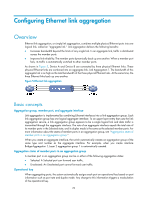
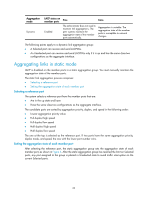
Configuring Ethernet link aggregation Overview Ethernet link aggregation, or simply link aggregation, combines multiple physical Ethernet ports into one logical link, called an "aggregate link." Link aggregation delivers the following benefits: • Increases bandwidth beyond the limits of any single link. In an aggregate link, traffic is distributed across the member ports. • Improves link reliability. The member ports dynamically back up one another. When a member port fails, its traffic is automatically switched to other member ports. As shown in Figure 5, Device A and Device B are connected by three physical Ethernet links. These physical Ethernet links are combined into an aggregate link, Link Aggregation 1. The bandwidth of this aggregate link is as high as the total bandwidth of the three physical Ethernet links. At the same time, the three Ethernet links back up one another. Figure 5 Ethernet link aggregation Basic concepts Aggregation group, member port, and aggregate interface Link aggregation is implemented by combining Ethernet interfaces into a link aggregation group. Each link aggregation group has one logical aggregate interface. To an upper layer entity that uses the link aggregation service, a link aggregation group appears to be a single logical link and data traffic is transmitted through the aggregate interface. The rate of an aggregate interface equals the total rate of its member ports in the Selected state, and its duplex mode is the same as the selected member ports. For more information about the states of member ports in an aggregation group, see "Aggregation states of member ports in an aggregation group." When you create an aggregate interface, the switch automatically creates an aggregation group of the same type and number as the aggregate interface. For example, when you create interface Bridge-Aggregation 1, Layer 2 aggregation group 1 is automatically created. Aggregation states of member ports in an aggregation group A member port in an aggregation group can be in either of the following aggregation states: • Selected: A Selected port can forward user traffic. • Unselected: An Unselected port cannot forward user traffic. Operational key When aggregating ports, the system automatically assigns each port an operational key based on port information such as port rate and duplex mode. Any change to this information triggers a recalculation of the operational key. 29
-
 1
1 -
2
-
3
-
4
-
5
-
6
-
7
-
8
-
9
-
10
-
11
-
12
-
13
-
14
-
15
-
16
-
17
-
18
-
19
-
20
-
21
-
22
-
23
-
24
-
25
-
26
-
27
-
28
-
29
-
30
-
31
-
32
-
 33
33 -
 34
34 -
 35
35 -
 36
36 -
 37
37 -
 38
38 -
 39
39 -
 40
40 -
 41
41 -
 42
42 -
 43
43 -
44
-
45
-
46
-
47
-
48
-
49
-
50
-
51
-
52
-
53
-
54
-
55
-
56
-
57
-
58
-
59
-
60
-
61
-
62
-
63
-
64
-
65
-
66
-
67
-
68
-
69
-
70
-
71
-
72
-
73
-
74
-
75
-
76
-
77
-
78
-
79
-
80
-
81
-
82
-
83
-
84
-
85
-
86
-
87
-
88
-
89
-
90
-
91
-
92
-
93
-
94
-
95
-
96
-
97
-
98
-
99
-
100
-
101
-
102
-
103
-
104
-
105
-
106
-
107
-
108
-
109
-
110
-
111
-
112
-
113
-
114
-
115
-
116
-
117
-
118
-
119
-
120
-
121
-
122
-
123
-
124
-
125
-
126
-
127
-
128
-
129
-
130
-
131
-
132
-
133
-
134
-
135
-
136
-
137
-
138
-
139
-
140
-
141
-
142
-
143
-
144
-
145
-
146
-
147
-
148
-
149
-
150
-
151
-
152
-
153
-
154
-
155
-
156
-
157
-
158
-
159
-
160
-
161
-
162
-
163
-
164
-
165
-
166
-
167
-
168
-
169
-
170
-
171
-
172
-
173
-
174
-
175
-
176
-
177
-
178
-
179
-
180
-
181
-
182
-
183
-
184
-
185
-
186
-
187
-
188
-
189
-
190
-
191
-
192
-
193
-
194
-
195
-
196
-
197
-
198
-
199
-
200
-
201
-
202
-
203
-
204
-
205
-
206
-
207
-
208
-
209
-
210
-
211
-
212
-
213
-
214
-
215
-
216
-
217
-
218
-
219
-
220
-
221
-
222
-
223
-
224
-
225
-
226
-
227
-
228
-
229
-
230
-
231
 |
 |
