HP 6125G HP 6125G & 6125G/XG Blade Switches Layer 2 - LAN Switching Co - Page 218
CDP-compatible LLDP configuration example, Network requirements
 |
View all HP 6125G manuals
Add to My Manuals
Save this manual to your list of manuals |
Page 218 highlights
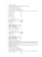
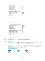
Hold multiplier Reinit delay Transmit delay Trap interval Fast start times : 4 : 2s : 2s : 5s : 3 Port 1 [GigabitEthernet1/0/1]: Port status of LLDP : Enable Admin status : Rx_Only Trap flag : No Polling interval : 0s Number of neighbors : 1 Number of MED neighbors : 1 Number of CDP neighbors : 0 Number of sent optional TLV : 0 Number of received unknown TLV : 5 Port 2 [GigabitEthernet1/0/2]: Port status of LLDP : Enable Admin status : Rx_Only Trap flag : No Polling interval : 0s Number of neighbors : 0 Number of MED neighbors : 0 Number of CDP neighbors : 0 Number of sent optional TLV : 0 Number of received unknown TLV : 0 As the sample output shows, GigabitEthernet 1/0/2 of Switch A does not connect to any neighboring devices. CDP-compatible LLDP configuration example Network requirements As shown in Figure 69, GigabitEthernet 1/0/1 and GigabitEthernet 1/0/2 of Switch A are each connected to a Cisco IP phone. The two IP phones send out tagged voice traffic. Configure voice VLAN 2 on Switch A. Enable CDP compatibility of LLDP on Switch A to allow the Cisco IP phones to automatically configure the voice VLAN, confining their voice traffic within the voice VLAN and isolating the voice traffic from other types of traffic. Figure 69 Network diagram 209
-
 1
1 -
2
-
3
-
4
-
5
-
6
-
7
-
8
-
9
-
10
-
11
-
12
-
13
-
14
-
15
-
16
-
17
-
18
-
19
-
20
-
21
-
22
-
23
-
24
-
25
-
26
-
27
-
28
-
29
-
30
-
31
-
32
-
33
-
34
-
35
-
36
-
37
-
38
-
39
-
40
-
41
-
42
-
43
-
44
-
45
-
46
-
47
-
48
-
49
-
50
-
51
-
52
-
53
-
54
-
55
-
56
-
57
-
58
-
59
-
60
-
61
-
62
-
63
-
64
-
65
-
66
-
67
-
68
-
69
-
70
-
71
-
72
-
73
-
74
-
75
-
76
-
77
-
78
-
79
-
80
-
81
-
82
-
83
-
84
-
85
-
86
-
87
-
88
-
89
-
90
-
91
-
92
-
93
-
94
-
95
-
96
-
97
-
98
-
99
-
100
-
101
-
102
-
103
-
104
-
105
-
106
-
107
-
108
-
109
-
110
-
111
-
112
-
113
-
114
-
115
-
116
-
117
-
118
-
119
-
120
-
121
-
122
-
123
-
124
-
125
-
126
-
127
-
128
-
129
-
130
-
131
-
132
-
133
-
134
-
135
-
136
-
137
-
138
-
139
-
140
-
141
-
142
-
143
-
144
-
145
-
146
-
147
-
148
-
149
-
150
-
151
-
152
-
153
-
154
-
155
-
156
-
157
-
158
-
159
-
160
-
161
-
162
-
163
-
164
-
165
-
166
-
167
-
168
-
169
-
170
-
171
-
172
-
173
-
174
-
175
-
176
-
177
-
178
-
179
-
180
-
181
-
182
-
183
-
184
-
185
-
186
-
187
-
188
-
189
-
190
-
191
-
192
-
193
-
194
-
195
-
196
-
197
-
198
-
199
-
200
-
201
-
202
-
203
-
204
-
205
-
206
-
207
-
208
-
209
-
210
-
211
-
212
-
 213
213 -
 214
214 -
 215
215 -
 216
216 -
 217
217 -
 218
218 -
 219
219 -
 220
220 -
 221
221 -
 222
222 -
 223
223 -
224
-
225
-
226
-
227
-
228
-
229
-
230
-
231
 |
 |