HP 6125G HP 6125G & 6125G/XG Blade Switches Layer 2 - LAN Switching Co - Page 20
Enabling bridging on an Ethernet interface, Testing the cable connection of an Ethernet interface
 |
View all HP 6125G manuals
Add to My Manuals
Save this manual to your list of manuals |
Page 20 highlights
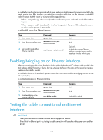
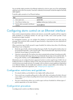
To enable the interface to communicate with its peer, make sure that its transmit pins are connected to the remote receive pins. If the interface can detect the connection cable type, set the interface in auto MDI mode. If not, set its MDI mode by using the following guidelines: • When a straight-through cable is used, set the interface to operate in the MDI mode different than its peer. • When a crossover cable is used, set the interface to operate in the same MDI mode as its peer, or set either end to operate in auto mode. To set the MDI mode of an Ethernet interface: Step 1. Enter system view. 2. Enter Ethernet interface view. Command system-view interface interface-type interface-number 3. Set the MDI mode of the Ethernet interface. mdi { across | auto | normal } Remarks N/A N/A Optional. By default, a copper Ethernet interface operates in auto mode to negotiate pin roles with its peer. Enabling bridging on an Ethernet interface When an incoming packet arrives, the device looks up the destination MAC address of the packet in the MAC address table. If an entry is found, but the outgoing interface is the same as the receiving interface, the device discards the packet. To enable the device to forward such packets rather than drop them, enable the bridging function on the Ethernet interface. To enable bridging on an Ethernet interface: Step 1. Enter system view. 2. Enter Ethernet interface view. 3. Enable bridging on the Ethernet interface. Command system-view interface interface-type interface-number port bridge enable Remarks N/A N/A Disabled by default. Testing the cable connection of an Ethernet interface IMPORTANT: • Fiber ports and internal Ethernet interfaces do not support this feature. • If the link of an Ethernet port is up, testing its cable connection will cause the link to come down and then go up. 11
-
 1
1 -
2
-
3
-
4
-
5
-
6
-
7
-
8
-
9
-
10
-
11
-
12
-
13
-
14
-
 15
15 -
 16
16 -
 17
17 -
 18
18 -
 19
19 -
 20
20 -
 21
21 -
 22
22 -
 23
23 -
 24
24 -
 25
25 -
26
-
27
-
28
-
29
-
30
-
31
-
32
-
33
-
34
-
35
-
36
-
37
-
38
-
39
-
40
-
41
-
42
-
43
-
44
-
45
-
46
-
47
-
48
-
49
-
50
-
51
-
52
-
53
-
54
-
55
-
56
-
57
-
58
-
59
-
60
-
61
-
62
-
63
-
64
-
65
-
66
-
67
-
68
-
69
-
70
-
71
-
72
-
73
-
74
-
75
-
76
-
77
-
78
-
79
-
80
-
81
-
82
-
83
-
84
-
85
-
86
-
87
-
88
-
89
-
90
-
91
-
92
-
93
-
94
-
95
-
96
-
97
-
98
-
99
-
100
-
101
-
102
-
103
-
104
-
105
-
106
-
107
-
108
-
109
-
110
-
111
-
112
-
113
-
114
-
115
-
116
-
117
-
118
-
119
-
120
-
121
-
122
-
123
-
124
-
125
-
126
-
127
-
128
-
129
-
130
-
131
-
132
-
133
-
134
-
135
-
136
-
137
-
138
-
139
-
140
-
141
-
142
-
143
-
144
-
145
-
146
-
147
-
148
-
149
-
150
-
151
-
152
-
153
-
154
-
155
-
156
-
157
-
158
-
159
-
160
-
161
-
162
-
163
-
164
-
165
-
166
-
167
-
168
-
169
-
170
-
171
-
172
-
173
-
174
-
175
-
176
-
177
-
178
-
179
-
180
-
181
-
182
-
183
-
184
-
185
-
186
-
187
-
188
-
189
-
190
-
191
-
192
-
193
-
194
-
195
-
196
-
197
-
198
-
199
-
200
-
201
-
202
-
203
-
204
-
205
-
206
-
207
-
208
-
209
-
210
-
211
-
212
-
213
-
214
-
215
-
216
-
217
-
218
-
219
-
220
-
221
-
222
-
223
-
224
-
225
-
226
-
227
-
228
-
229
-
230
-
231
 |
 |