HP 6125G HP 6125G & 6125G/XG Blade Switches Layer 2 - LAN Switching Co - Page 68
MST region, MSTI, VLAN-to-instance mapping table, CST, Regional root
 |
View all HP 6125G manuals
Add to My Manuals
Save this manual to your list of manuals |
Page 68 highlights
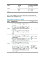
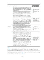
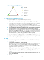
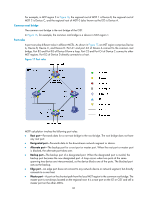
MST region A multiple spanning tree region (MST region) consists of multiple devices in a switched network and the network segments among them. All these devices have the following characteristics: • A spanning tree protocol enabled • Same region name • Same VLAN-to-instance mapping configuration • Same MSTP revision level • Physically linked together Multiple MST regions can exist in a switched network. You can assign multiple devices to the same MST region. In Figure 15, the switched network comprises four MST regions, MST region 1 through MST region 4, and all devices in each MST region have the same MST region configuration. MSTI MSTP can generate multiple independent spanning trees in an MST region, and each spanning tree is mapped to the specific VLANs. Each spanning tree is referred to as a multiple spanning tree instance (MSTI). In Figure 16, MST region 3 comprises three MSTIs, MSTI 1, MSTI 2, and MSTI 0. VLAN-to-instance mapping table As an attribute of an MST region, the VLAN-to-instance mapping table describes the mapping relationships between VLANs and MSTIs. In Figure 16, the VLAN-to-instance mapping table of MST region 3 is: VLAN 1 to MSTI 1, VLAN 2 and VLAN 3 to MSTI 2, and other VLANs to MSTI 0. MSTP achieves load balancing by means of the VLAN-to-instance mapping table. CST The common spanning tree (CST) is a single spanning tree that connects all MST regions in a switched network. If you regard each MST region as a device, the CST is a spanning tree calculated by these devices through STP or RSTP. The blue lines in Figure 15 represent the CST. IST An internal spanning tree (IST) is a spanning tree that runs in an MST region. It is also called MSTI 0, a special MSTI to which all VLANs are mapped by default. In Figure 15, MSTI 0 is the IST in MST region 3. CIST The common and internal spanning tree (CIST) is a single spanning tree that connects all devices in a switched network. It consists of the ISTs in all MST regions and the CST. In Figure 15, the ISTs (MSTI 0) in all MST regions plus the inter-region CST constitute the CIST of the entire network. Regional root The root bridge of the IST or an MSTI within an MST region is the regional root of the IST or MSTI. Based on the topology, different spanning trees in an MST region might have different regional roots. 59
-
 1
1 -
2
-
3
-
4
-
5
-
6
-
7
-
8
-
9
-
10
-
11
-
12
-
13
-
14
-
15
-
16
-
17
-
18
-
19
-
20
-
21
-
22
-
23
-
24
-
25
-
26
-
27
-
28
-
29
-
30
-
31
-
32
-
33
-
34
-
35
-
36
-
37
-
38
-
39
-
40
-
41
-
42
-
43
-
44
-
45
-
46
-
47
-
48
-
49
-
50
-
51
-
52
-
53
-
54
-
55
-
56
-
57
-
58
-
59
-
60
-
61
-
62
-
 63
63 -
 64
64 -
 65
65 -
 66
66 -
 67
67 -
 68
68 -
 69
69 -
 70
70 -
 71
71 -
 72
72 -
 73
73 -
74
-
75
-
76
-
77
-
78
-
79
-
80
-
81
-
82
-
83
-
84
-
85
-
86
-
87
-
88
-
89
-
90
-
91
-
92
-
93
-
94
-
95
-
96
-
97
-
98
-
99
-
100
-
101
-
102
-
103
-
104
-
105
-
106
-
107
-
108
-
109
-
110
-
111
-
112
-
113
-
114
-
115
-
116
-
117
-
118
-
119
-
120
-
121
-
122
-
123
-
124
-
125
-
126
-
127
-
128
-
129
-
130
-
131
-
132
-
133
-
134
-
135
-
136
-
137
-
138
-
139
-
140
-
141
-
142
-
143
-
144
-
145
-
146
-
147
-
148
-
149
-
150
-
151
-
152
-
153
-
154
-
155
-
156
-
157
-
158
-
159
-
160
-
161
-
162
-
163
-
164
-
165
-
166
-
167
-
168
-
169
-
170
-
171
-
172
-
173
-
174
-
175
-
176
-
177
-
178
-
179
-
180
-
181
-
182
-
183
-
184
-
185
-
186
-
187
-
188
-
189
-
190
-
191
-
192
-
193
-
194
-
195
-
196
-
197
-
198
-
199
-
200
-
201
-
202
-
203
-
204
-
205
-
206
-
207
-
208
-
209
-
210
-
211
-
212
-
213
-
214
-
215
-
216
-
217
-
218
-
219
-
220
-
221
-
222
-
223
-
224
-
225
-
226
-
227
-
228
-
229
-
230
-
231
 |
 |