HP 6125G HP 6125G & 6125G/XG Blade Switches Layer 2 - LAN Switching Co - Page 185
Concepts and terms, Site 1 and Site 2 are in VLAN 2 and VLAN 3
 |
View all HP 6125G manuals
Add to My Manuals
Save this manual to your list of manuals |
Page 185 highlights
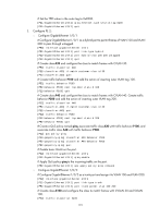
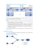
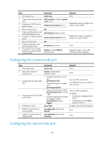
Figure 57 Application scenario of one-to-two and two-to-two VLAN mapping Site 1 and Site 2 are in VLAN 2 and VLAN 3, respectively. The VLAN assigned for VPN A is VLAN 10 in the SP 1 network and VLAN 20 in the SP 2 network. If Site 1 sends a packet to Site 2, the packet is processed on the way to its destination using the following workflow: 1. When the packet tagged with VLAN 2 arrives at the edge of network SP 1, PE 1 tags the packet with outer VLAN 10 by using one-to-two VLAN mapping. 2. When the double-tagged packet enters the SP 2 network, PE 3 replaces the outer VLAN tag (VLAN 10) with VLAN 20. Because the packet is destined for Site 2 in VLAN 3, PE 3 also replaces the inner tag (VLAN 2) of the packet with VLAN 3. This process is two-to-two VLAN mapping. 3. When PE4 receives the packet with the new VLAN tag pair, it removes the outer VLAN tag and forwards the packet to VLAN 3. You can use QinQ to implement one-to-two VLAN mapping. For more information about QinQ, see "Configuring QinQ." Concepts and terms Figure 58 shows a simplified network to help explain the concepts and terms that you might encounter when you work with VLAN mapping. Figure 58 Basic concepts of VLAN mapping 176 SP Network-side port Customer-side port Uplink traffic Downlink traffic
-
 1
1 -
2
-
3
-
4
-
5
-
6
-
7
-
8
-
9
-
10
-
11
-
12
-
13
-
14
-
15
-
16
-
17
-
18
-
19
-
20
-
21
-
22
-
23
-
24
-
25
-
26
-
27
-
28
-
29
-
30
-
31
-
32
-
33
-
34
-
35
-
36
-
37
-
38
-
39
-
40
-
41
-
42
-
43
-
44
-
45
-
46
-
47
-
48
-
49
-
50
-
51
-
52
-
53
-
54
-
55
-
56
-
57
-
58
-
59
-
60
-
61
-
62
-
63
-
64
-
65
-
66
-
67
-
68
-
69
-
70
-
71
-
72
-
73
-
74
-
75
-
76
-
77
-
78
-
79
-
80
-
81
-
82
-
83
-
84
-
85
-
86
-
87
-
88
-
89
-
90
-
91
-
92
-
93
-
94
-
95
-
96
-
97
-
98
-
99
-
100
-
101
-
102
-
103
-
104
-
105
-
106
-
107
-
108
-
109
-
110
-
111
-
112
-
113
-
114
-
115
-
116
-
117
-
118
-
119
-
120
-
121
-
122
-
123
-
124
-
125
-
126
-
127
-
128
-
129
-
130
-
131
-
132
-
133
-
134
-
135
-
136
-
137
-
138
-
139
-
140
-
141
-
142
-
143
-
144
-
145
-
146
-
147
-
148
-
149
-
150
-
151
-
152
-
153
-
154
-
155
-
156
-
157
-
158
-
159
-
160
-
161
-
162
-
163
-
164
-
165
-
166
-
167
-
168
-
169
-
170
-
171
-
172
-
173
-
174
-
175
-
176
-
177
-
178
-
179
-
 180
180 -
 181
181 -
 182
182 -
 183
183 -
 184
184 -
 185
185 -
 186
186 -
 187
187 -
 188
188 -
 189
189 -
 190
190 -
191
-
192
-
193
-
194
-
195
-
196
-
197
-
198
-
199
-
200
-
201
-
202
-
203
-
204
-
205
-
206
-
207
-
208
-
209
-
210
-
211
-
212
-
213
-
214
-
215
-
216
-
217
-
218
-
219
-
220
-
221
-
222
-
223
-
224
-
225
-
226
-
227
-
228
-
229
-
230
-
231
 |
 |
