HP 6125G HP 6125G & 6125G/XG Blade Switches Layer 2 - LAN Switching Co - Page 67
MSTP basic concepts,
 |
View all HP 6125G manuals
Add to My Manuals
Save this manual to your list of manuals |
Page 67 highlights
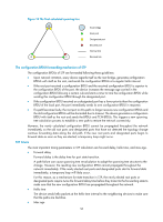
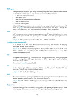
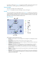
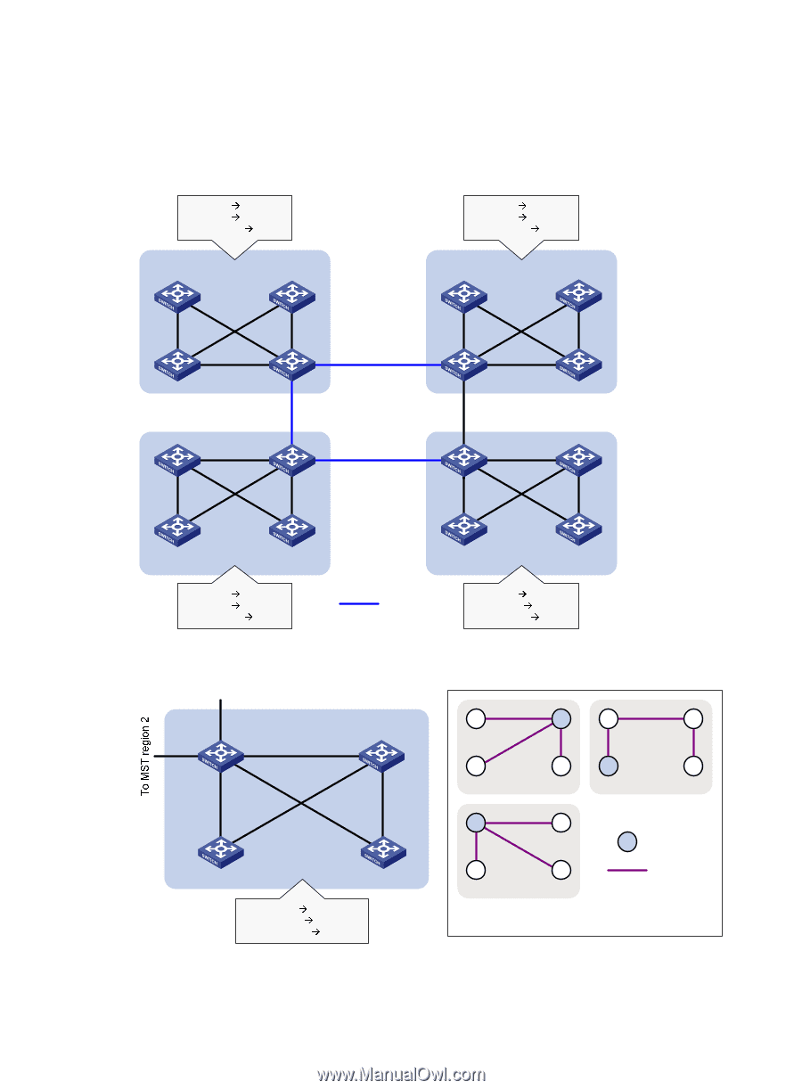
MSTP basic concepts Figure 15 shows a switched network that comprises four MST regions, each MST region comprising four MSTP devices. Figure 16 shows the networking topology of MST region 3. Figure 15 Basic concepts in MSTP VLAN 1 MSTI 1 VLAN 2 MSTI 2 Other VLANs MSTI 0 VLAN 1 MSTI 1 VLAN 2 MSTI 2 Other VLANs MSTI 0 MST region 1 MST region 4 MST region 2 VLAN 1 MSTI 1 VLAN 2 MSTI 2 Other VLANs MSTI 0 CST MST region 3 VLAN 1 MSTI 1 VLAN 2&3 MSTI 2 Other VLANs MSTI 0 Figure 16 Network diagram and topology of MST region 3 To MST region 4 MST region 3 A B Device A Device B C D MSTI 1 A B C D MSTI 2 Device C Device D VLAN 1 MSTI 1 VLAN 2&3 MSTI 2 Other VLANs MSTI 0 A B C D MSTI 0 Regional root MSTI Topology of MSTIs in MST region 3 58
-
 1
1 -
2
-
3
-
4
-
5
-
6
-
7
-
8
-
9
-
10
-
11
-
12
-
13
-
14
-
15
-
16
-
17
-
18
-
19
-
20
-
21
-
22
-
23
-
24
-
25
-
26
-
27
-
28
-
29
-
30
-
31
-
32
-
33
-
34
-
35
-
36
-
37
-
38
-
39
-
40
-
41
-
42
-
43
-
44
-
45
-
46
-
47
-
48
-
49
-
50
-
51
-
52
-
53
-
54
-
55
-
56
-
57
-
58
-
59
-
60
-
61
-
 62
62 -
 63
63 -
 64
64 -
 65
65 -
 66
66 -
 67
67 -
 68
68 -
 69
69 -
 70
70 -
 71
71 -
 72
72 -
73
-
74
-
75
-
76
-
77
-
78
-
79
-
80
-
81
-
82
-
83
-
84
-
85
-
86
-
87
-
88
-
89
-
90
-
91
-
92
-
93
-
94
-
95
-
96
-
97
-
98
-
99
-
100
-
101
-
102
-
103
-
104
-
105
-
106
-
107
-
108
-
109
-
110
-
111
-
112
-
113
-
114
-
115
-
116
-
117
-
118
-
119
-
120
-
121
-
122
-
123
-
124
-
125
-
126
-
127
-
128
-
129
-
130
-
131
-
132
-
133
-
134
-
135
-
136
-
137
-
138
-
139
-
140
-
141
-
142
-
143
-
144
-
145
-
146
-
147
-
148
-
149
-
150
-
151
-
152
-
153
-
154
-
155
-
156
-
157
-
158
-
159
-
160
-
161
-
162
-
163
-
164
-
165
-
166
-
167
-
168
-
169
-
170
-
171
-
172
-
173
-
174
-
175
-
176
-
177
-
178
-
179
-
180
-
181
-
182
-
183
-
184
-
185
-
186
-
187
-
188
-
189
-
190
-
191
-
192
-
193
-
194
-
195
-
196
-
197
-
198
-
199
-
200
-
201
-
202
-
203
-
204
-
205
-
206
-
207
-
208
-
209
-
210
-
211
-
212
-
213
-
214
-
215
-
216
-
217
-
218
-
219
-
220
-
221
-
222
-
223
-
224
-
225
-
226
-
227
-
228
-
229
-
230
-
231
 |
 |
58
MSTP basic concepts
Figure 15
shows a switched network that comprises four MST regions, each MST region comprising four
MSTP devices.
Figure 16
shows the networking topology of MST region 3.
Figure 15
Basic concepts in MSTP
Figure 16
Network diagram and topology of MST region 3
MST region 1
MST region 2
MST region 3
MST region 4
VLAN 1
MSTI 1
VLAN 2
MSTI 2
Other VLANs
MSTI 0
VLAN 1
MSTI 1
VLAN 2
MSTI 2
Other VLANs
MSTI 0
VLAN 1
MSTI 1
VLAN 2
MSTI 2
Other VLANs
MSTI 0
VLAN 1
MSTI 1
VLAN 2&3
MSTI 2
Other VLANs
MSTI 0
CST
MST region 3
Device A
Device C
Device B
Device D
VLAN 1
MSTI 1
VLAN 2&3
MSTI 2
Other VLANs
MSTI 0
To MST region 4
B
A
C
D
MSTI 1
A
B
C
D
MSTI 0
B
D
MSTI 2
C
A
Regional root
MSTI
Topology of MSTIs in MST region 3