HP 6125G HP 6125G & 6125G/XG Blade Switches Layer 2 - LAN Switching Co - Page 94
Enabling root guard, Fundamentals Configuration Guide
 |
View all HP 6125G manuals
Add to My Manuals
Save this manual to your list of manuals |
Page 94 highlights
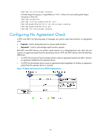
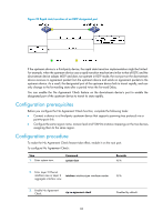
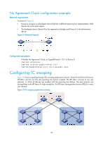
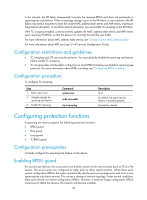
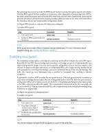
The spanning tree protocol provides the BPDU guard function to protect the system against such attacks. With the BPDU guard function enabled on the devices, when edge ports receive configuration BPDUs, the system closes these ports and notifies the NMS that these ports have been closed by the spanning tree protocol. The device will reactivate the closed ports after a detection interval. For more information about this detection interval, see Fundamentals Configuration Guide. Configure BPDU guard on a device with edge ports configured. To enable BPDU guard: Step 1. Enter system view. 2. Enable the BPDU guard function for the device. Command system-view stp bpdu-protection Remarks N/A Disabled by default. NOTE: BPDU guard does not take effect on loopback-testing-enabled ports. For more information about loopback testing, see "Configuring Ethernet interfaces." Enabling root guard The root bridge and secondary root bridge of a spanning tree should be located in the same MST region. Especially for the CIST, the root bridge and secondary root bridge are put in a high-bandwidth core region during network design. However, due to possible configuration errors or malicious attacks in the network, the legal root bridge might receive a configuration BPDU with a higher priority. Another device will supersede the current legal root bridge, causing an undesired change of the network topology. The traffic that should go over high-speed links is switched to low-speed links, resulting in network congestion. To prevent this situation, MSTP provides the root guard function. If the root guard function is enabled on a port of a root bridge, this port plays the role of designated port on all MSTIs. After this port receives a configuration BPDU with a higher priority from an MSTI, it immediately sets that port to the listening state in the MSTI, without forwarding the packet. This is equivalent to disconnecting the link connected with this port in the MSTI. If the port receives no BPDUs with a higher priority within twice the forwarding delay, it reverts to its original state. Configure root guard on a designated port. To enable root guard: Step 1. Enter system view. 2. Enter Layer 2 Ethernet interface view or Layer 2 aggregate interface view. 3. Enable the root guard function for the ports. Command system-view interface interface-type interface-number stp root-protection Remarks N/A N/A Disabled by default. NOTE: You cannot configure root guard and loop guard on a port at the same time. 85
-
 1
1 -
2
-
3
-
4
-
5
-
6
-
7
-
8
-
9
-
10
-
11
-
12
-
13
-
14
-
15
-
16
-
17
-
18
-
19
-
20
-
21
-
22
-
23
-
24
-
25
-
26
-
27
-
28
-
29
-
30
-
31
-
32
-
33
-
34
-
35
-
36
-
37
-
38
-
39
-
40
-
41
-
42
-
43
-
44
-
45
-
46
-
47
-
48
-
49
-
50
-
51
-
52
-
53
-
54
-
55
-
56
-
57
-
58
-
59
-
60
-
61
-
62
-
63
-
64
-
65
-
66
-
67
-
68
-
69
-
70
-
71
-
72
-
73
-
74
-
75
-
76
-
77
-
78
-
79
-
80
-
81
-
82
-
83
-
84
-
85
-
86
-
87
-
88
-
 89
89 -
 90
90 -
 91
91 -
 92
92 -
 93
93 -
 94
94 -
 95
95 -
 96
96 -
 97
97 -
 98
98 -
 99
99 -
100
-
101
-
102
-
103
-
104
-
105
-
106
-
107
-
108
-
109
-
110
-
111
-
112
-
113
-
114
-
115
-
116
-
117
-
118
-
119
-
120
-
121
-
122
-
123
-
124
-
125
-
126
-
127
-
128
-
129
-
130
-
131
-
132
-
133
-
134
-
135
-
136
-
137
-
138
-
139
-
140
-
141
-
142
-
143
-
144
-
145
-
146
-
147
-
148
-
149
-
150
-
151
-
152
-
153
-
154
-
155
-
156
-
157
-
158
-
159
-
160
-
161
-
162
-
163
-
164
-
165
-
166
-
167
-
168
-
169
-
170
-
171
-
172
-
173
-
174
-
175
-
176
-
177
-
178
-
179
-
180
-
181
-
182
-
183
-
184
-
185
-
186
-
187
-
188
-
189
-
190
-
191
-
192
-
193
-
194
-
195
-
196
-
197
-
198
-
199
-
200
-
201
-
202
-
203
-
204
-
205
-
206
-
207
-
208
-
209
-
210
-
211
-
212
-
213
-
214
-
215
-
216
-
217
-
218
-
219
-
220
-
221
-
222
-
223
-
224
-
225
-
226
-
227
-
228
-
229
-
230
-
231
 |
 |