HP 6125G HP 6125G & 6125G/XG Blade Switches Layer 2 - LAN Switching Co - Page 135
Configuration restrictions and guidelines, Configuration procedure, secondary VLAN interfaces.
 |
View all HP 6125G manuals
Add to My Manuals
Save this manual to your list of manuals |
Page 135 highlights
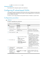
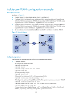
{ Configure the downlink ports, for example, the ports connecting Device B to hosts in Figure 38, to operate in host mode, so that the downlink ports can be added to the isolate-user-VLAN associated with the secondary VLAN automatically. For more information about the promiscuous and host mode commands, see Layer 2-LAN Switching Command Reference. Configuration restrictions and guidelines • After you complete the Configuration procedure, make sure that the isolate-user-VLAN is the PVID of the upstream port and the secondary VLAN is the PVID of the downstream port. For hybrid ports that have been assigned to the isolate-user-VLAN and secondary VLANs in tagged mode, HP recommends that you assign these ports to these VLANs in untagged mode. • To enable users in the isolate-user-VLAN to communicate with other networks at Layer 3, Configure VLAN interfaces for the isolate-user-VLAN and the secondary VLANs, and configure the gateway IP address for the isolate-user-VLAN interface (you do not need to configure IP addresses for the secondary VLAN interfaces). • The dynamic MAC addresses entries learned in the isolate-user-VLAN are automatically synchronized to all the secondary VLANs, and the dynamic MAC address entries learned in a secondary VLAN are automatically synchronized to the isolate-user-VLAN. Static MAC address entries cannot be automatically synchronized. If you have configured static MAC address entries in the isolate-user-VLAN, you should also configure the same static MAC address entries in the secondary VLANs to avoid broadcasts, and vice versa. • You cannot configure the member port of a service loopback group as the uplink or downlink port of an isolate-user-VLAN. For more information about the service loopback group, see "Configuring a service loopback group." Configuration procedure To configure an isolate-user-VLAN: Step 1. Enter system view. 2. Create a VLAN and enter VLAN view. 3. Configure the VLAN as an isolate-user-VLAN. 4. Return to system view. 5. Create secondary VLANs. 6. Return to system view. 7. Associate the isolate-user-VLAN with the specified secondary VLANs. Command system-view vlan vlan-id Remarks N/A N/A isolate-user-vlan enable Not configured by default. quit N/A vlan { vlan-id1 [ to vlan-id2 ] | all } N/A quit N/A isolate-user-vlan isolate-user-vlan-id secondary secondary-vlan-id [ to secondary-vlan-id ] Not configured by default. 126
-
 1
1 -
2
-
3
-
4
-
5
-
6
-
7
-
8
-
9
-
10
-
11
-
12
-
13
-
14
-
15
-
16
-
17
-
18
-
19
-
20
-
21
-
22
-
23
-
24
-
25
-
26
-
27
-
28
-
29
-
30
-
31
-
32
-
33
-
34
-
35
-
36
-
37
-
38
-
39
-
40
-
41
-
42
-
43
-
44
-
45
-
46
-
47
-
48
-
49
-
50
-
51
-
52
-
53
-
54
-
55
-
56
-
57
-
58
-
59
-
60
-
61
-
62
-
63
-
64
-
65
-
66
-
67
-
68
-
69
-
70
-
71
-
72
-
73
-
74
-
75
-
76
-
77
-
78
-
79
-
80
-
81
-
82
-
83
-
84
-
85
-
86
-
87
-
88
-
89
-
90
-
91
-
92
-
93
-
94
-
95
-
96
-
97
-
98
-
99
-
100
-
101
-
102
-
103
-
104
-
105
-
106
-
107
-
108
-
109
-
110
-
111
-
112
-
113
-
114
-
115
-
116
-
117
-
118
-
119
-
120
-
121
-
122
-
123
-
124
-
125
-
126
-
127
-
128
-
129
-
 130
130 -
 131
131 -
 132
132 -
 133
133 -
 134
134 -
 135
135 -
 136
136 -
 137
137 -
 138
138 -
 139
139 -
 140
140 -
141
-
142
-
143
-
144
-
145
-
146
-
147
-
148
-
149
-
150
-
151
-
152
-
153
-
154
-
155
-
156
-
157
-
158
-
159
-
160
-
161
-
162
-
163
-
164
-
165
-
166
-
167
-
168
-
169
-
170
-
171
-
172
-
173
-
174
-
175
-
176
-
177
-
178
-
179
-
180
-
181
-
182
-
183
-
184
-
185
-
186
-
187
-
188
-
189
-
190
-
191
-
192
-
193
-
194
-
195
-
196
-
197
-
198
-
199
-
200
-
201
-
202
-
203
-
204
-
205
-
206
-
207
-
208
-
209
-
210
-
211
-
212
-
213
-
214
-
215
-
216
-
217
-
218
-
219
-
220
-
221
-
222
-
223
-
224
-
225
-
226
-
227
-
228
-
229
-
230
-
231
 |
 |
