HP 6125G HP 6125G & 6125G/XG Blade Switches Layer 2 - LAN Switching Co - Page 176
Configuration procedure
 |
View all HP 6125G manuals
Add to My Manuals
Save this manual to your list of manuals |
Page 176 highlights
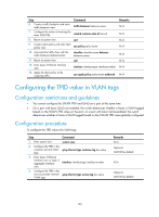
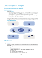
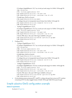
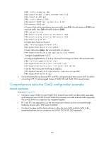
• The two branches of a company, Site 1 and Site 2, are connected through the service provider network and use CVLAN 10 and CVLAN 20 to transmit voice traffic and data traffic separately. • PE 1 and PE 2 are edge devices on the service provider network and are connected through third-party devices with a TPID value of 0x8200. • Configure the edge and third-party devices to allow frames from CVLAN 10 to be transmitted between the branches via SVLAN 100 and frames from CVLAN 20 to be transmitted between the branches via SVLAN 200. Figure 54 Network diagram Configuration procedure IMPORTANT: Make sure that you have configured the switches in the service provider network to allow QinQ packets to pass through. 1. Configure PE 1: { Configure GigabitEthernet 1/0/1: # Configure GigabitEthernet 1/0/1 as a hybrid port to permit frames of VLAN 100 and VLAN 200 to pass through untagged. system-view [PE1] interface gigabitethernet 1/0/1 [PE1-GigabitEthernet1/0/1] port link-type hybrid [PE1-GigabitEthernet1/0/1] port hybrid vlan 100 200 untagged [PE1-GigabitEthernet1/0/1] quit # Create class A10 and configure the class to match frames from Site 1 with CVLAN 10. [PE1] traffic classifier A10 [PE1-classifier-A10] if-match customer-vlan-id 10 [PE1-classifier-A10] quit # Create traffic behavior P100 and add the action of inserting outer VLAN tag 100. [PE1] traffic behavior P100 [PE1-behavior-P100] nest top-most vlan-id 100 167
-
 1
1 -
2
-
3
-
4
-
5
-
6
-
7
-
8
-
9
-
10
-
11
-
12
-
13
-
14
-
15
-
16
-
17
-
18
-
19
-
20
-
21
-
22
-
23
-
24
-
25
-
26
-
27
-
28
-
29
-
30
-
31
-
32
-
33
-
34
-
35
-
36
-
37
-
38
-
39
-
40
-
41
-
42
-
43
-
44
-
45
-
46
-
47
-
48
-
49
-
50
-
51
-
52
-
53
-
54
-
55
-
56
-
57
-
58
-
59
-
60
-
61
-
62
-
63
-
64
-
65
-
66
-
67
-
68
-
69
-
70
-
71
-
72
-
73
-
74
-
75
-
76
-
77
-
78
-
79
-
80
-
81
-
82
-
83
-
84
-
85
-
86
-
87
-
88
-
89
-
90
-
91
-
92
-
93
-
94
-
95
-
96
-
97
-
98
-
99
-
100
-
101
-
102
-
103
-
104
-
105
-
106
-
107
-
108
-
109
-
110
-
111
-
112
-
113
-
114
-
115
-
116
-
117
-
118
-
119
-
120
-
121
-
122
-
123
-
124
-
125
-
126
-
127
-
128
-
129
-
130
-
131
-
132
-
133
-
134
-
135
-
136
-
137
-
138
-
139
-
140
-
141
-
142
-
143
-
144
-
145
-
146
-
147
-
148
-
149
-
150
-
151
-
152
-
153
-
154
-
155
-
156
-
157
-
158
-
159
-
160
-
161
-
162
-
163
-
164
-
165
-
166
-
167
-
168
-
169
-
170
-
 171
171 -
 172
172 -
 173
173 -
 174
174 -
 175
175 -
 176
176 -
 177
177 -
 178
178 -
 179
179 -
 180
180 -
 181
181 -
182
-
183
-
184
-
185
-
186
-
187
-
188
-
189
-
190
-
191
-
192
-
193
-
194
-
195
-
196
-
197
-
198
-
199
-
200
-
201
-
202
-
203
-
204
-
205
-
206
-
207
-
208
-
209
-
210
-
211
-
212
-
213
-
214
-
215
-
216
-
217
-
218
-
219
-
220
-
221
-
222
-
223
-
224
-
225
-
226
-
227
-
228
-
229
-
230
-
231
 |
 |
