HP 6125G HP 6125G & 6125G/XG Blade Switches Layer 2 - LAN Switching Co - Page 147
Voice VLAN configuration examples, Automatic voice VLAN mode configuration example
 |
View all HP 6125G manuals
Add to My Manuals
Save this manual to your list of manuals |
Page 147 highlights
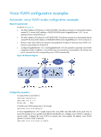
Voice VLAN configuration examples Automatic voice VLAN mode configuration example Network requirements As shown in Figure 42, • The MAC address of IP phone A is 0011-1100-0001. The phone connects to a downstream device named PC A whose MAC address is 0022-1100-0002 and to GigabitEthernet 1/0/1 on an upstream device named Device A. • The MAC address of IP phone B is 0011-2200-0001. The phone connects to a downstream device named PC B whose MAC address is 0022-2200-0002 and to GigabitEthernet 1/0/2 on Device A. • Device A uses voice VLAN 2 to transmit voice packets for IP phone A and uses voice VLAN 3 to transmit voice packets for IP phone B. • Configure GigabitEthernet 1/0/1 and GigabitEthernet 1/0/2 to operate in automatic voice VLAN assignment mode. In addition, if one of them has not received any voice packet in 30 minutes, the port is removed from the corresponding voice VLAN automatically. Figure 42 Network diagram Configuration procedure # Create VLAN 2 and VLAN 3. system-view [DeviceA] vlan 2 to 3 Please wait... Done. # Set the voice VLAN aging time to 30 minutes. [DeviceA] voice vlan aging 30 # Since GigabitEthernet 1/0/1 might receive both voice traffic and data traffic at the same time, to ensure the quality of voice packets and effective bandwidth use, configure voice VLANs to operate in security mode. Configure the voice VLANs to transmit only voice packets. By default, voice VLANs operate in security mode. (Optional) [DeviceA] voice vlan security enable 138
-
 1
1 -
2
-
3
-
4
-
5
-
6
-
7
-
8
-
9
-
10
-
11
-
12
-
13
-
14
-
15
-
16
-
17
-
18
-
19
-
20
-
21
-
22
-
23
-
24
-
25
-
26
-
27
-
28
-
29
-
30
-
31
-
32
-
33
-
34
-
35
-
36
-
37
-
38
-
39
-
40
-
41
-
42
-
43
-
44
-
45
-
46
-
47
-
48
-
49
-
50
-
51
-
52
-
53
-
54
-
55
-
56
-
57
-
58
-
59
-
60
-
61
-
62
-
63
-
64
-
65
-
66
-
67
-
68
-
69
-
70
-
71
-
72
-
73
-
74
-
75
-
76
-
77
-
78
-
79
-
80
-
81
-
82
-
83
-
84
-
85
-
86
-
87
-
88
-
89
-
90
-
91
-
92
-
93
-
94
-
95
-
96
-
97
-
98
-
99
-
100
-
101
-
102
-
103
-
104
-
105
-
106
-
107
-
108
-
109
-
110
-
111
-
112
-
113
-
114
-
115
-
116
-
117
-
118
-
119
-
120
-
121
-
122
-
123
-
124
-
125
-
126
-
127
-
128
-
129
-
130
-
131
-
132
-
133
-
134
-
135
-
136
-
137
-
138
-
139
-
140
-
141
-
 142
142 -
 143
143 -
 144
144 -
 145
145 -
 146
146 -
 147
147 -
 148
148 -
 149
149 -
 150
150 -
 151
151 -
 152
152 -
153
-
154
-
155
-
156
-
157
-
158
-
159
-
160
-
161
-
162
-
163
-
164
-
165
-
166
-
167
-
168
-
169
-
170
-
171
-
172
-
173
-
174
-
175
-
176
-
177
-
178
-
179
-
180
-
181
-
182
-
183
-
184
-
185
-
186
-
187
-
188
-
189
-
190
-
191
-
192
-
193
-
194
-
195
-
196
-
197
-
198
-
199
-
200
-
201
-
202
-
203
-
204
-
205
-
206
-
207
-
208
-
209
-
210
-
211
-
212
-
213
-
214
-
215
-
216
-
217
-
218
-
219
-
220
-
221
-
222
-
223
-
224
-
225
-
226
-
227
-
228
-
229
-
230
-
231
 |
 |
