HP 6125G HP 6125G & 6125G/XG Blade Switches Layer 2 - LAN Switching Co - Page 70
Port states, How MSTP works, CIST calculation
 |
View all HP 6125G manuals
Add to My Manuals
Save this manual to your list of manuals |
Page 70 highlights
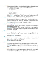
• Boundary port-Connects an MST region to another MST region or to an STP/RSTP-running device. In MSTP calculation, a boundary port's role on an MSTI is consistent with its role on the CIST. But that is not true with master ports. A master port on MSTIs is a root port on the CIST. Port states In MSTP, a port can be in one of the following states: • Forwarding-The port receives and sends BPDUs, obtains MAC addresses, and forwards user traffic. • Learning-The port receives and sends BPDUs, obtains MAC addresses, but does not forward user traffic. Learning is an intermediate port state. • Discarding-The port receives and sends BPDUs, but does not obtain MAC addresses or forward user traffic. When in different MSTIs, a port can be in different states. A port state is not exclusively associated with a port role. Table 12 lists the port states that each port role supports. (A check mark [√] indicates that the port supports this state, while a dash [-] indicates that the port does not support this state.) Table 12 Port states that different port roles support Port role (right) Port state (below) Forwarding Learning Discarding Root port/master port √ √ √ Designated port √ √ √ Alternate port - - √ Backup port - - √ How MSTP works MSTP divides an entire Layer 2 network into multiple MST regions, which are connected by a calculated CST. Inside an MST region, multiple spanning trees are calculated. Each spanning tree is an MSTI. Among these MSTIs, MSTI 0 is the IST. Like STP, MSTP uses configuration BPDUs to calculate spanning trees. An important difference is that an MSTP BPDU carries the MSTP configuration of the bridge from which the BPDU is sent. CIST calculation The calculation of a CIST tree is also the process of configuration BPDU comparison. During this process, the device with the highest priority is elected as the root bridge of the CIST. MSTP generates an IST within each MST region through calculation. At the same time, MSTP regards each MST region as a single device and generates a CST among these MST regions through calculation. The CST and ISTs constitute the CIST of the entire network. MSTI calculation Within an MST region, MSTP generates different MSTIs for different VLANs based on the VLAN-to-instance mappings. For each spanning tree, MSTP performs a separate calculation process similar to spanning tree calculation in STP. For more information, see "Calculation process of the STP algorithm." In MSTP, a VLAN packet is forwarded along the following paths: • Within an MST region, the packet is forwarded along the corresponding MSTI. 61
-
 1
1 -
2
-
3
-
4
-
5
-
6
-
7
-
8
-
9
-
10
-
11
-
12
-
13
-
14
-
15
-
16
-
17
-
18
-
19
-
20
-
21
-
22
-
23
-
24
-
25
-
26
-
27
-
28
-
29
-
30
-
31
-
32
-
33
-
34
-
35
-
36
-
37
-
38
-
39
-
40
-
41
-
42
-
43
-
44
-
45
-
46
-
47
-
48
-
49
-
50
-
51
-
52
-
53
-
54
-
55
-
56
-
57
-
58
-
59
-
60
-
61
-
62
-
63
-
64
-
 65
65 -
 66
66 -
 67
67 -
 68
68 -
 69
69 -
 70
70 -
 71
71 -
 72
72 -
 73
73 -
 74
74 -
 75
75 -
76
-
77
-
78
-
79
-
80
-
81
-
82
-
83
-
84
-
85
-
86
-
87
-
88
-
89
-
90
-
91
-
92
-
93
-
94
-
95
-
96
-
97
-
98
-
99
-
100
-
101
-
102
-
103
-
104
-
105
-
106
-
107
-
108
-
109
-
110
-
111
-
112
-
113
-
114
-
115
-
116
-
117
-
118
-
119
-
120
-
121
-
122
-
123
-
124
-
125
-
126
-
127
-
128
-
129
-
130
-
131
-
132
-
133
-
134
-
135
-
136
-
137
-
138
-
139
-
140
-
141
-
142
-
143
-
144
-
145
-
146
-
147
-
148
-
149
-
150
-
151
-
152
-
153
-
154
-
155
-
156
-
157
-
158
-
159
-
160
-
161
-
162
-
163
-
164
-
165
-
166
-
167
-
168
-
169
-
170
-
171
-
172
-
173
-
174
-
175
-
176
-
177
-
178
-
179
-
180
-
181
-
182
-
183
-
184
-
185
-
186
-
187
-
188
-
189
-
190
-
191
-
192
-
193
-
194
-
195
-
196
-
197
-
198
-
199
-
200
-
201
-
202
-
203
-
204
-
205
-
206
-
207
-
208
-
209
-
210
-
211
-
212
-
213
-
214
-
215
-
216
-
217
-
218
-
219
-
220
-
221
-
222
-
223
-
224
-
225
-
226
-
227
-
228
-
229
-
230
-
231
 |
 |