Intel S2600CP Technical Product Specification - Page 111
FAN Connectors
 |
View all Intel S2600CP manuals
Add to My Manuals
Save this manual to your list of manuals |
Page 111 highlights
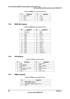
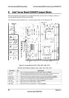
Intel® Server Board S2600CP and Server System P4000CP TPS Intel® Server Board S2600CP Connector/Header Locations and Pin-outs Pin 5 P3V3 Signal name 7.4.5 Chassis Intrusion Header The server board includes a 2-pin chassis intrusion header which can be used when the chassis is configured with a chassis intrusion switch. The header has the following pin-out. Table 46. Chassis Intrusion Header Pin-out Header State Pins 1 and 2 closed Pins 1 and 2 open Description FM_INTRUDER_HDR_N is pulled HIGH. Chassis cover is closed. FM_INTRUDER_HDR_N is pulled LOW. Chassis cover is removed. 7.4.6 IPMB Connector Table 47. IPMB Connector Pin-out Pin Signal Name 1 SMB_IPMB_5VSTBY_DATA 2 GND 3 SMB_IPMB_5VSTBY_CLK 4 P5V_STBY 7.5 FAN Connectors The server board provides support for nine fans. Seven of them are system cooling fans, two of them are CPU fans. 7.5.1 System FAN Connectors The six system cooling fan connectors near the front edge of the board are 6-Pin connectors; the one system cooling fan near edge of the board is a 4-Pin connectors. Following table provides the pin-out for all system fan connectors. Table 48. 6-pin System FAN Connector Pin-out Pin Signal Name 1 GND 2 12V 3 TACH 4 PWM 5 PRSNT 6 FAULT Table 49. 4-pin System FAN Connector Pin-out Pin Signal Name 1 GND 2 12V 3 TACH 4 PWM Revision 1.2 95 Intel order number G26942-003
-
 1
1 -
2
-
3
-
4
-
5
-
6
-
7
-
8
-
9
-
10
-
11
-
12
-
13
-
14
-
15
-
16
-
17
-
18
-
19
-
20
-
21
-
22
-
23
-
24
-
25
-
26
-
27
-
28
-
29
-
30
-
31
-
32
-
33
-
34
-
35
-
36
-
37
-
38
-
39
-
40
-
41
-
42
-
43
-
44
-
45
-
46
-
47
-
48
-
49
-
50
-
51
-
52
-
53
-
54
-
55
-
56
-
57
-
58
-
59
-
60
-
61
-
62
-
63
-
64
-
65
-
66
-
67
-
68
-
69
-
70
-
71
-
72
-
73
-
74
-
75
-
76
-
77
-
78
-
79
-
80
-
81
-
82
-
83
-
84
-
85
-
86
-
87
-
88
-
89
-
90
-
91
-
92
-
93
-
94
-
95
-
96
-
97
-
98
-
99
-
100
-
101
-
102
-
103
-
104
-
105
-
 106
106 -
 107
107 -
 108
108 -
 109
109 -
 110
110 -
 111
111 -
 112
112 -
 113
113 -
 114
114 -
 115
115 -
 116
116 -
117
-
118
-
119
-
120
-
121
-
122
-
123
-
124
-
125
-
126
-
127
-
128
-
129
-
130
-
131
-
132
-
133
-
134
-
135
-
136
-
137
-
138
-
139
-
140
-
141
-
142
-
143
-
144
-
145
-
146
-
147
-
148
-
149
-
150
-
151
-
152
-
153
-
154
-
155
-
156
-
157
-
158
-
159
-
160
-
161
-
162
-
163
-
164
-
165
-
166
-
167
-
168
-
169
-
170
-
171
-
172
-
173
-
174
-
175
-
176
-
177
-
178
-
179
-
180
-
181
-
182
-
183
-
184
-
185
-
186
-
187
-
188
-
189
-
190
-
191
-
192
-
193
-
194
-
195
-
196
-
197
-
198
-
199
-
200
-
201
-
202
-
203
-
204
-
205
-
206
-
207
-
208
-
209
-
210
-
211
-
212
-
213
-
214
-
215
-
216
-
217
-
218
-
219
-
220
-
221
-
222
-
223
-
224
-
225
-
226
-
227
-
228
 |
 |