Intel S2600CP Technical Product Specification - Page 175
Intel S2600CP Manual
 |
View all Intel S2600CP manuals
Add to My Manuals
Save this manual to your list of manuals |
Page 175 highlights
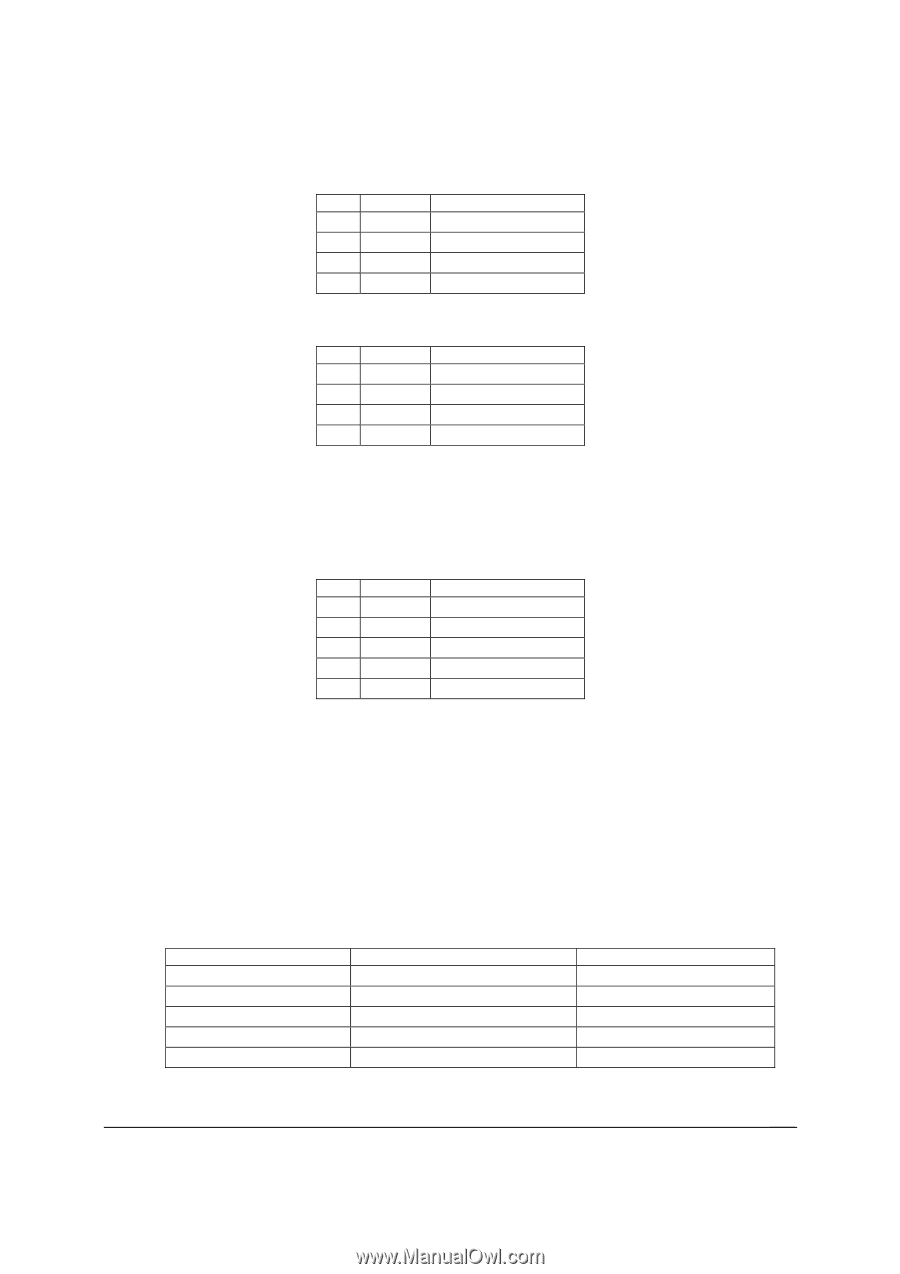
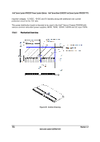
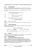
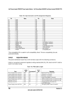
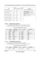
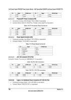
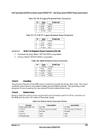
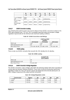
Intel® Server Board S2600CP and Server System P4000CP TPS Intel® Server System P4000CP Power System Options Table 120. P8, P9 Legacy Peripheral Power Connectors Pin Signal 1 +12V3 18 AWG Color Green 2 COM Black 3 COM Black 4 +5 VDC Red Table 121. P7, P10, P11 Legacy Peripheral Power Connectors Pin Signal 1 +12V3 18 AWG Color Green 2 COM Black 3 COM Black 4 +5 VDC Red 13.4.2.2.7 SATA 1x5 Peripheral Power Connectors (P5, P6) Connector housing: Molex* 0675-82-0000 or equivalent Contact: Molex* 0675-81-0000 or equivalent Table 122. SATA Peripheral Power Connectors Pin Signal 18 AWG Color 1 +3.3VDC Orange 2 COM Black 3 +5VDC Red 4 COM Black 5 +12V2 Yellow 13.4.2.3 Grounding The ground of the pins of the PDB output connectors provides the power return path. The output connector ground pins is connected to safety ground (PDB enclosure). This grounding is well designed to ensure passing the max allowed Common Mode Noise levels. 13.4.2.4 Remote Sense Below is listed the remote sense requirements and connection points for all the converters on the PDB and the main 12V output of the power supply. Table 123. Remote Sense Connection Points Converter Power supply main 12V 12V/3.3V 12V/5V 12V/-12V 12Vstby/5Vstby + sense location On PDB P20 (1x5 signal connector) On PDB none none - sense location On PDB P20 (1x5 signal connector) On PDB none none Revision 1.2 159 Intel order number G26942-003
-
 1
1 -
2
-
3
-
4
-
5
-
6
-
7
-
8
-
9
-
10
-
11
-
12
-
13
-
14
-
15
-
16
-
17
-
18
-
19
-
20
-
21
-
22
-
23
-
24
-
25
-
26
-
27
-
28
-
29
-
30
-
31
-
32
-
33
-
34
-
35
-
36
-
37
-
38
-
39
-
40
-
41
-
42
-
43
-
44
-
45
-
46
-
47
-
48
-
49
-
50
-
51
-
52
-
53
-
54
-
55
-
56
-
57
-
58
-
59
-
60
-
61
-
62
-
63
-
64
-
65
-
66
-
67
-
68
-
69
-
70
-
71
-
72
-
73
-
74
-
75
-
76
-
77
-
78
-
79
-
80
-
81
-
82
-
83
-
84
-
85
-
86
-
87
-
88
-
89
-
90
-
91
-
92
-
93
-
94
-
95
-
96
-
97
-
98
-
99
-
100
-
101
-
102
-
103
-
104
-
105
-
106
-
107
-
108
-
109
-
110
-
111
-
112
-
113
-
114
-
115
-
116
-
117
-
118
-
119
-
120
-
121
-
122
-
123
-
124
-
125
-
126
-
127
-
128
-
129
-
130
-
131
-
132
-
133
-
134
-
135
-
136
-
137
-
138
-
139
-
140
-
141
-
142
-
143
-
144
-
145
-
146
-
147
-
148
-
149
-
150
-
151
-
152
-
153
-
154
-
155
-
156
-
157
-
158
-
159
-
160
-
161
-
162
-
163
-
164
-
165
-
166
-
167
-
168
-
169
-
 170
170 -
 171
171 -
 172
172 -
 173
173 -
 174
174 -
 175
175 -
 176
176 -
 177
177 -
 178
178 -
 179
179 -
 180
180 -
181
-
182
-
183
-
184
-
185
-
186
-
187
-
188
-
189
-
190
-
191
-
192
-
193
-
194
-
195
-
196
-
197
-
198
-
199
-
200
-
201
-
202
-
203
-
204
-
205
-
206
-
207
-
208
-
209
-
210
-
211
-
212
-
213
-
214
-
215
-
216
-
217
-
218
-
219
-
220
-
221
-
222
-
223
-
224
-
225
-
226
-
227
-
228
 |
 |