Intel S2600CP Technical Product Specification - Page 177
DC/DC Converters Loading, 4.2.8, 5VSB Loading, 4.2.9, DC/DC Converters Voltage Regulation
 |
View all Intel S2600CP manuals
Add to My Manuals
Save this manual to your list of manuals |
Page 177 highlights
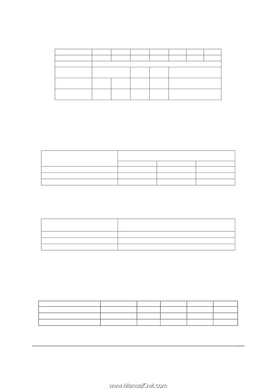
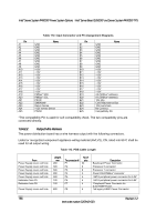
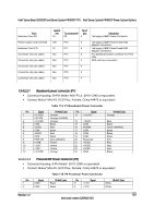
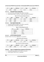
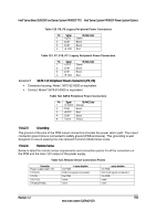
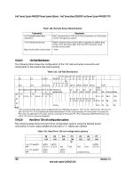
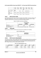
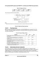
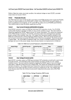
Intel® Server Board S2600CP and Server System P4000CP TPS Intel® Server System P4000CP Power System Options P8 P9 P10 P11 P5 P6 P7 1x4 1x4 1x4 1x4 1x5 1x5 1x4 1 x 3.5" 8xHDD BP HDD1 8x3.5 18 N/a N/a peripheral bay 8 x 3.5" fixed SATA 2xfixed 2xfixed 2xfixed 2xfixed peripheral bay 8 x 3.5" fixed SAS 2xfixed 2xfixed 2xfixed 2xfixed peripheral bay 13.4.2.7 DC/DC Converters Loading The following table defines power and current ratings of three DC/DC converters located on the PDB, each powered from +12V rail. The 3 converters meet both static and dynamic voltage regulation requirements for the minimum and maximum loading conditions. Table 127. DC/DC Converters Load Ratings MAX Load MIN Static/Dynamic Load Max Output Power +3.3V Converter 25A 0A 3.3V x25A =82.5W +12VDC Input DC/DC Converters +5V Converter 25A 0A 5V x25A =125W -12V Converter 0.5A 0A 12V x0.5A =6W 13.4.2.8 5VSB Loading There is also one DC/DC converter that converts the 12V standby into 5V standby. Table 128. 5VSB Loading MAX Load MIN Static/Dynamic Load Max Output Power 8A 0.1 5V x8A =40W 12V stby/5V stby DC/DC Converters 13.4.2.9 DC/DC Converters Voltage Regulation The DC/DC converters' output voltages stay within the following voltage limits when operating at steady state and dynamic loading conditions. These limits include the peak-peak ripple/noise specified in Table 145. The 3.3V and 5V outputs are measured at the remote sense point, all other voltages measured at the output harness connectors. Table 129. Voltage Regulation Limits Converter output + 3.3VDC + 5VDC 5Vstby Tolerance -4%/+5% -4%/+5% -4%/+5% Min +3.20 +4.80 +4.80 Nom +3.30 +5.00 +5.00 Max +3.46 +5.25 +5.25 Units VDC VDC VDC Revision 1.2 161 Intel order number G26942-003
-
 1
1 -
2
-
3
-
4
-
5
-
6
-
7
-
8
-
9
-
10
-
11
-
12
-
13
-
14
-
15
-
16
-
17
-
18
-
19
-
20
-
21
-
22
-
23
-
24
-
25
-
26
-
27
-
28
-
29
-
30
-
31
-
32
-
33
-
34
-
35
-
36
-
37
-
38
-
39
-
40
-
41
-
42
-
43
-
44
-
45
-
46
-
47
-
48
-
49
-
50
-
51
-
52
-
53
-
54
-
55
-
56
-
57
-
58
-
59
-
60
-
61
-
62
-
63
-
64
-
65
-
66
-
67
-
68
-
69
-
70
-
71
-
72
-
73
-
74
-
75
-
76
-
77
-
78
-
79
-
80
-
81
-
82
-
83
-
84
-
85
-
86
-
87
-
88
-
89
-
90
-
91
-
92
-
93
-
94
-
95
-
96
-
97
-
98
-
99
-
100
-
101
-
102
-
103
-
104
-
105
-
106
-
107
-
108
-
109
-
110
-
111
-
112
-
113
-
114
-
115
-
116
-
117
-
118
-
119
-
120
-
121
-
122
-
123
-
124
-
125
-
126
-
127
-
128
-
129
-
130
-
131
-
132
-
133
-
134
-
135
-
136
-
137
-
138
-
139
-
140
-
141
-
142
-
143
-
144
-
145
-
146
-
147
-
148
-
149
-
150
-
151
-
152
-
153
-
154
-
155
-
156
-
157
-
158
-
159
-
160
-
161
-
162
-
163
-
164
-
165
-
166
-
167
-
168
-
169
-
170
-
171
-
 172
172 -
 173
173 -
 174
174 -
 175
175 -
 176
176 -
 177
177 -
 178
178 -
 179
179 -
 180
180 -
 181
181 -
 182
182 -
183
-
184
-
185
-
186
-
187
-
188
-
189
-
190
-
191
-
192
-
193
-
194
-
195
-
196
-
197
-
198
-
199
-
200
-
201
-
202
-
203
-
204
-
205
-
206
-
207
-
208
-
209
-
210
-
211
-
212
-
213
-
214
-
215
-
216
-
217
-
218
-
219
-
220
-
221
-
222
-
223
-
224
-
225
-
226
-
227
-
228
 |
 |