Intel S2600CP Technical Product Specification - Page 138
Intel, Server System P4000CP Thermal Management
 |
View all Intel S2600CP manuals
Add to My Manuals
Save this manual to your list of manuals |
Page 138 highlights
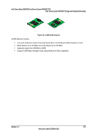
Intel® Server System P4000CP Thermal Management Intel® Server Board S2600CP and Server System P4000CP TPS 12. Intel® Server System P4000CP Thermal Management The Intel® Server System P4000CP is designed to operate at external ambient temperatures in compliance with ASHARE class A2.. Working with integrated platform management, several features within the system are designed to move air in a front to back direction, through the system and over critical components in order to prevent them from overheating and allow the system to operate with best performance. 12.1 Thermal Operation and Configuration Requirements To keep the system operating within supported maximum thermal limits, the system must meet the following operating and configuration guidelines: Operating Ambient temperature must be compliant with ASHARE Class A2 guidance. All hard drive bays must be populated. Hard drive carriers either can be populated with a hard drive or supplied drive blank. The air duct must be installed at all times. In single power supply configurations, the second power supply bay must have the supplied filler blank installed at all times. The system top-cover must be installed at all times. 12.2 Thermal Management Overview In order to maintain comprehensive thermal protection and meanwhile deliver best system acoustic as well as fan power efficiency, an intelligent Fan Speed Control (FSC) and thermal management technology (mechanism) is developed. Options reserved for end users to adjust parameter settings based on the actual system configuration and usage in BIOS interface with path: BIOS > Advanced > System Acoustic and Performance Configuration. Refer the following sections in order to setup the system thermally correct. 12.2.1 Set Throttling Mode Select the most appropriate memory thermal throttling mechanism for memory sub-system from [Auto], [DCLTT], [SCLTT] and [SOLTT]. [Auto] - BIOS automatically detect and identify the appropriate thermal throttling mechanism based on DIMM type, airflow input, DIMM sensor availability. [DCLTT] - Dynamic Closed Loop Thermal Throttling: for the SOD DIMM with system airflow input [SCLTT] - Static Close Loop Thermal Throttling: for the SOD DIMM without system airflow input [SOLTT] - Static Open Loop Thermal Throttling: for the DIMMs without sensor on dimm (SOD) The default setting is [Auto]. 12.2.2 Altitude Select the proper altitude that the system is distributed from [300m or less], [301m-900m], [901m-1500m], [Above 1500m] options. Lower altitude selection can lead to potential thermal risk. And higher altitude selection provides better cooling but with undesired acoustic and fan power consumption. If the altitude is known, higher altitude is recommended in order to provide sufficient cooling. The default setting is [301m - 900m]. 122 Revision 1.2 Intel order number G26942-003
-
 1
1 -
2
-
3
-
4
-
5
-
6
-
7
-
8
-
9
-
10
-
11
-
12
-
13
-
14
-
15
-
16
-
17
-
18
-
19
-
20
-
21
-
22
-
23
-
24
-
25
-
26
-
27
-
28
-
29
-
30
-
31
-
32
-
33
-
34
-
35
-
36
-
37
-
38
-
39
-
40
-
41
-
42
-
43
-
44
-
45
-
46
-
47
-
48
-
49
-
50
-
51
-
52
-
53
-
54
-
55
-
56
-
57
-
58
-
59
-
60
-
61
-
62
-
63
-
64
-
65
-
66
-
67
-
68
-
69
-
70
-
71
-
72
-
73
-
74
-
75
-
76
-
77
-
78
-
79
-
80
-
81
-
82
-
83
-
84
-
85
-
86
-
87
-
88
-
89
-
90
-
91
-
92
-
93
-
94
-
95
-
96
-
97
-
98
-
99
-
100
-
101
-
102
-
103
-
104
-
105
-
106
-
107
-
108
-
109
-
110
-
111
-
112
-
113
-
114
-
115
-
116
-
117
-
118
-
119
-
120
-
121
-
122
-
123
-
124
-
125
-
126
-
127
-
128
-
129
-
130
-
131
-
132
-
 133
133 -
 134
134 -
 135
135 -
 136
136 -
 137
137 -
 138
138 -
 139
139 -
 140
140 -
 141
141 -
 142
142 -
 143
143 -
144
-
145
-
146
-
147
-
148
-
149
-
150
-
151
-
152
-
153
-
154
-
155
-
156
-
157
-
158
-
159
-
160
-
161
-
162
-
163
-
164
-
165
-
166
-
167
-
168
-
169
-
170
-
171
-
172
-
173
-
174
-
175
-
176
-
177
-
178
-
179
-
180
-
181
-
182
-
183
-
184
-
185
-
186
-
187
-
188
-
189
-
190
-
191
-
192
-
193
-
194
-
195
-
196
-
197
-
198
-
199
-
200
-
201
-
202
-
203
-
204
-
205
-
206
-
207
-
208
-
209
-
210
-
211
-
212
-
213
-
214
-
215
-
216
-
217
-
218
-
219
-
220
-
221
-
222
-
223
-
224
-
225
-
226
-
227
-
228
 |
 |