Intel S2600CP Technical Product Specification - Page 159
Table 91. LED Characteristics, Table 92. Power Supply LED Functionality
 |
View all Intel S2600CP manuals
Add to My Manuals
Save this manual to your list of manuals |
Page 159 highlights
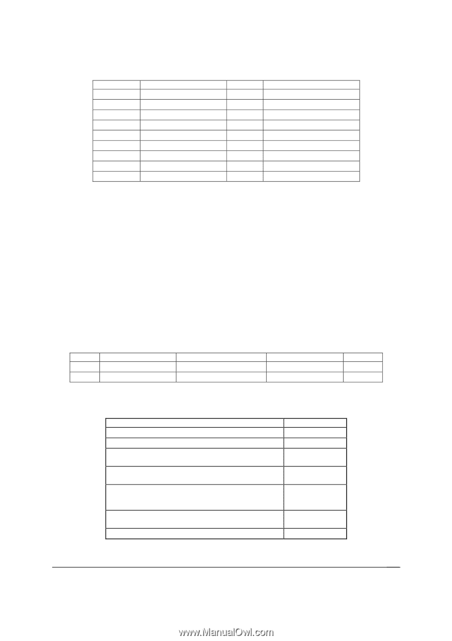
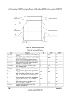
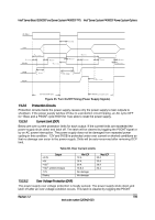
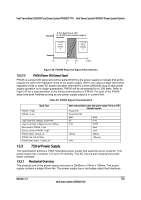
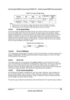
Intel® Server Board S2600CP and Server System P4000CP TPS Intel® Server System P4000CP Power System Options Pin A17 A18 A19 A20 A21 A22 A23 A24 A25 +12V Name +12V PMBus* SDA PMBus* SCL PSON SMBAlert# Return Sense +12V remote Sense PWOK Pin B17 B18 B19 B20 B21 B22 B23 B24 B25 +12V Name +12V A0 (SMBus* address) A1 (SMBus* address) 12V stby Cold Redundancy Bus 12V load share bus No Connect Compatibility Check pin 13.3.1.2 Handle Retention The power supply has a handle to assist extraction. The module is able to be inserted and extracted without the assistance of tools. The power supply has a latch which retains the power supply into the system and prevents the power supply from being inserted or extracted from the system when the AC power cord is pulled into the power supply. The handle protects the operator from any burn hazard. 13.3.1.3 LED Marking and Identification The power supply uses a bi-color LED: Amber and Green. Below are table showing the LED states for each power supply operating state and the LED's wavelength characteristics. Refer to the Intel LED Wavelength and Intensity specification for more details. Table 91. LED Characteristics Green Amber Min λd Wavelength 562 607 Nominal λd Wavelength 565 610 Max λd Wavelength 568 613 Units nm nm Table 92. Power Supply LED Functionality Power Supply Condition Output ON and OK No AC power to all power supplies AC present/Only 12VSB on (PS off) or PS in Cold redundant state AC cord unplugged or AC power lost; with a second power supply in parallel still with AC input power. Power supply warning events where the power supply continues to operate; high temp, high power, high current, slow fan. Power supply critical event causing a shutdown; failure, OCP, OVP, Fan Fail Power supply FW updating LED State GREEN OFF 1Hz Blink GREEN AMBER 1Hz Blink Amber AMBER 2Hz Blink GREEN Revision 1.2 143 Intel order number G26942-003
-
 1
1 -
2
-
3
-
4
-
5
-
6
-
7
-
8
-
9
-
10
-
11
-
12
-
13
-
14
-
15
-
16
-
17
-
18
-
19
-
20
-
21
-
22
-
23
-
24
-
25
-
26
-
27
-
28
-
29
-
30
-
31
-
32
-
33
-
34
-
35
-
36
-
37
-
38
-
39
-
40
-
41
-
42
-
43
-
44
-
45
-
46
-
47
-
48
-
49
-
50
-
51
-
52
-
53
-
54
-
55
-
56
-
57
-
58
-
59
-
60
-
61
-
62
-
63
-
64
-
65
-
66
-
67
-
68
-
69
-
70
-
71
-
72
-
73
-
74
-
75
-
76
-
77
-
78
-
79
-
80
-
81
-
82
-
83
-
84
-
85
-
86
-
87
-
88
-
89
-
90
-
91
-
92
-
93
-
94
-
95
-
96
-
97
-
98
-
99
-
100
-
101
-
102
-
103
-
104
-
105
-
106
-
107
-
108
-
109
-
110
-
111
-
112
-
113
-
114
-
115
-
116
-
117
-
118
-
119
-
120
-
121
-
122
-
123
-
124
-
125
-
126
-
127
-
128
-
129
-
130
-
131
-
132
-
133
-
134
-
135
-
136
-
137
-
138
-
139
-
140
-
141
-
142
-
143
-
144
-
145
-
146
-
147
-
148
-
149
-
150
-
151
-
152
-
153
-
 154
154 -
 155
155 -
 156
156 -
 157
157 -
 158
158 -
 159
159 -
 160
160 -
 161
161 -
 162
162 -
 163
163 -
 164
164 -
165
-
166
-
167
-
168
-
169
-
170
-
171
-
172
-
173
-
174
-
175
-
176
-
177
-
178
-
179
-
180
-
181
-
182
-
183
-
184
-
185
-
186
-
187
-
188
-
189
-
190
-
191
-
192
-
193
-
194
-
195
-
196
-
197
-
198
-
199
-
200
-
201
-
202
-
203
-
204
-
205
-
206
-
207
-
208
-
209
-
210
-
211
-
212
-
213
-
214
-
215
-
216
-
217
-
218
-
219
-
220
-
221
-
222
-
223
-
224
-
225
-
226
-
227
-
228
 |
 |