Intel S2600CP Technical Product Specification - Page 173
Baseboard power connector P1, Processor#0 Power Connector P2
 |
View all Intel S2600CP manuals
Add to My Manuals
Save this manual to your list of manuals |
Page 173 highlights
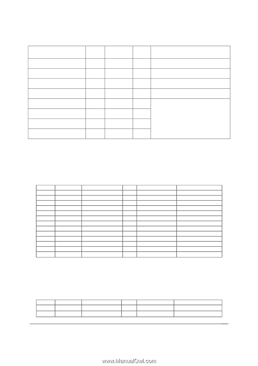
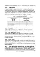
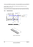
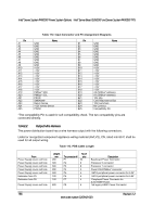
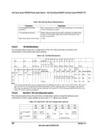
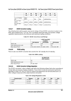
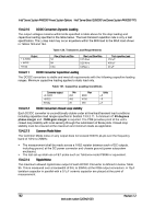
Intel® Server Board S2600CP and Server System P4000CP TPS Intel® Server System P4000CP Power System Options From Extension from P8 Power supply cover exit hole Extension from P10 Connector only (no cable) Connector only (no cable) Connector only (no cable) Connector only (no cable) Connector only (no cable) Length, mm 75 To connector # P9 No of pins 4 Description 1x4 legacy HSBP Power Connector 700 P10 75 P11 N/a P12 N/a P13 4 1x4 legacy HSBP Power/Fixed HDD adaptor Connection 4 1x4 legacy HSBP Power/Fixed HDD adaptor Connection 4 Aux baseboard power connector for PCIe slots 4 GFX card aux connectors N/a P14 4 N/a P15 4 N/a P16 4 13.4.2.2.1 Baseboard power connector (P1) Connector housing: 24-Pin Molex* Mini-Fit Jr. 39-01-2245 or equivalent Contact: Molex* Mini-Fit, HCS Plus, Female, Crimp 44476 or equivalent Table 114. P1 Baseboard Power Connector Pin 1 2 3 4 5 6 7 8 9 10 11 12 Signal +3.3VDC 3.3V RS +3.3VDC COM +5VDC COM +5VDC COM PWR OK 5 VSB +12V1 +12V1 +3.3VDC 18 AWG Color Orange Orange (24AWG) Orange Black Red Black Red Black Gray (24AWG) Purple Yellow Yellow Orange Pin Signal 13 +3.3VDC 14 -12VDC 15 COM 16 PSON# 17 COM 18 COM 19 COM 20 Reserved 21 +5VDC 22 +5VDC 23 +5VDC 24 COM 18 AWG Color Orange Blue Black Green (24AWG) Black Black Black N.C. Red Red Red Black 13.4.2.2.2 Processor#0 Power Connector (P2) Connector housing: 8-Pin Molex* 39-01-2080 or equivalent Contact: Molex* Mini-Fit, HCS Plus, Female, Crimp 44476 or equivalent Table 115. P0 Processor Power Connector Pin 1 2 Signal COM COM 18 AWG color Black Black Pin Signal 5* +12V1 6 +12V1 18 AWG Color White White Revision 1.2 157 Intel order number G26942-003
-
 1
1 -
2
-
3
-
4
-
5
-
6
-
7
-
8
-
9
-
10
-
11
-
12
-
13
-
14
-
15
-
16
-
17
-
18
-
19
-
20
-
21
-
22
-
23
-
24
-
25
-
26
-
27
-
28
-
29
-
30
-
31
-
32
-
33
-
34
-
35
-
36
-
37
-
38
-
39
-
40
-
41
-
42
-
43
-
44
-
45
-
46
-
47
-
48
-
49
-
50
-
51
-
52
-
53
-
54
-
55
-
56
-
57
-
58
-
59
-
60
-
61
-
62
-
63
-
64
-
65
-
66
-
67
-
68
-
69
-
70
-
71
-
72
-
73
-
74
-
75
-
76
-
77
-
78
-
79
-
80
-
81
-
82
-
83
-
84
-
85
-
86
-
87
-
88
-
89
-
90
-
91
-
92
-
93
-
94
-
95
-
96
-
97
-
98
-
99
-
100
-
101
-
102
-
103
-
104
-
105
-
106
-
107
-
108
-
109
-
110
-
111
-
112
-
113
-
114
-
115
-
116
-
117
-
118
-
119
-
120
-
121
-
122
-
123
-
124
-
125
-
126
-
127
-
128
-
129
-
130
-
131
-
132
-
133
-
134
-
135
-
136
-
137
-
138
-
139
-
140
-
141
-
142
-
143
-
144
-
145
-
146
-
147
-
148
-
149
-
150
-
151
-
152
-
153
-
154
-
155
-
156
-
157
-
158
-
159
-
160
-
161
-
162
-
163
-
164
-
165
-
166
-
167
-
 168
168 -
 169
169 -
 170
170 -
 171
171 -
 172
172 -
 173
173 -
 174
174 -
 175
175 -
 176
176 -
 177
177 -
 178
178 -
179
-
180
-
181
-
182
-
183
-
184
-
185
-
186
-
187
-
188
-
189
-
190
-
191
-
192
-
193
-
194
-
195
-
196
-
197
-
198
-
199
-
200
-
201
-
202
-
203
-
204
-
205
-
206
-
207
-
208
-
209
-
210
-
211
-
212
-
213
-
214
-
215
-
216
-
217
-
218
-
219
-
220
-
221
-
222
-
223
-
224
-
225
-
226
-
227
-
228
 |
 |