Intel S2600CP Technical Product Specification - Page 139
Intel, Server System P4308CP4MHEN. - motherboard
 |
View all Intel S2600CP manuals
Add to My Manuals
Save this manual to your list of manuals |
Page 139 highlights
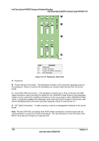
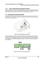
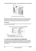
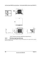
Intel® Server Board S2600CP and Server System P4000CP TPS Intel® Server System P4000CP Thermal Management 12.2.3 Set Fan Profile [Performance] and [Acoustic] fan profiles are available to select. The Acoustic mode offers best acoustic experience and appropriate cooling capability covering mainstream and majority of the add-in cards. Performance mode is designed to provide sufficient cooling capability covering all kinds of add-in cards on the market. The default setting is [Performance]. 12.2.4 Fan PWM Offset This feature is reserved for manual adjustment to the minimum fan speed curves. The valid range is from [0 to 100] which stands for 0% to 100% PWM adding to the minimum fan speed. This feature is valid when Quiet Fan Idle Mode is at Enabled state. The default setting is [0]. 12.2.5 Quiet Fan Idle Mode This feature can be [Enabled] or [Disabled]. If enabled, the fan will either stopped or shift to a lower speed when the aggregate sensor temperatures are satisfied indicating the system is at ideal thermal/light loading conditions. When the aggregate sensor temperatures not satisfied, the fan will shift back to normal control curves. If disabled, the fan will never stopped or shift into lower fan speed whatever the aggregate sensor temperatures are satisfied or not. The default setting is [Disabled] Note: The above features may or may not be in effective depends on the actual thermal characters of a specific system. Refer to specific system for additional information. 12.3 Intel® Server System P4308CP4MHEN. 12.3.1 Fan and HDD Configuration The Intel® Server System P4308CP4MHEN consists of two 120x38mm system fans and two passive CPU heatsinks providing cooling for all ingredients inside the enclosure. The two 120x38mm fans deliver different cooling capability and are not interchangeable. All the fans are Pulse Width Modulated (PWM) 4 wire/pin compatible fans. The fan headers are connected to motherboard with below sequence. Improper connection will potentially lead to thermal risk or undesired acoustic. SYS FAN 1 connect to PCI fan SYS FAN 2 connect to Core fan SYS FAN 3 reserved SYS FAN 4 reserved SYS FAN 5 reserved SYS FAN 6 reserved REAR FAN reserved Revision 1.2 123 Intel order number G26942-003
-
 1
1 -
2
-
3
-
4
-
5
-
6
-
7
-
8
-
9
-
10
-
11
-
12
-
13
-
14
-
15
-
16
-
17
-
18
-
19
-
20
-
21
-
22
-
23
-
24
-
25
-
26
-
27
-
28
-
29
-
30
-
31
-
32
-
33
-
34
-
35
-
36
-
37
-
38
-
39
-
40
-
41
-
42
-
43
-
44
-
45
-
46
-
47
-
48
-
49
-
50
-
51
-
52
-
53
-
54
-
55
-
56
-
57
-
58
-
59
-
60
-
61
-
62
-
63
-
64
-
65
-
66
-
67
-
68
-
69
-
70
-
71
-
72
-
73
-
74
-
75
-
76
-
77
-
78
-
79
-
80
-
81
-
82
-
83
-
84
-
85
-
86
-
87
-
88
-
89
-
90
-
91
-
92
-
93
-
94
-
95
-
96
-
97
-
98
-
99
-
100
-
101
-
102
-
103
-
104
-
105
-
106
-
107
-
108
-
109
-
110
-
111
-
112
-
113
-
114
-
115
-
116
-
117
-
118
-
119
-
120
-
121
-
122
-
123
-
124
-
125
-
126
-
127
-
128
-
129
-
130
-
131
-
132
-
133
-
 134
134 -
 135
135 -
 136
136 -
 137
137 -
 138
138 -
 139
139 -
 140
140 -
 141
141 -
 142
142 -
 143
143 -
 144
144 -
145
-
146
-
147
-
148
-
149
-
150
-
151
-
152
-
153
-
154
-
155
-
156
-
157
-
158
-
159
-
160
-
161
-
162
-
163
-
164
-
165
-
166
-
167
-
168
-
169
-
170
-
171
-
172
-
173
-
174
-
175
-
176
-
177
-
178
-
179
-
180
-
181
-
182
-
183
-
184
-
185
-
186
-
187
-
188
-
189
-
190
-
191
-
192
-
193
-
194
-
195
-
196
-
197
-
198
-
199
-
200
-
201
-
202
-
203
-
204
-
205
-
206
-
207
-
208
-
209
-
210
-
211
-
212
-
213
-
214
-
215
-
216
-
217
-
218
-
219
-
220
-
221
-
222
-
223
-
224
-
225
-
226
-
227
-
228
 |
 |
