Intel S2600CP Technical Product Specification - Page 125
Intel, Server System P4000CP Front Control Panel, and Back Panel
 |
View all Intel S2600CP manuals
Add to My Manuals
Save this manual to your list of manuals |
Page 125 highlights
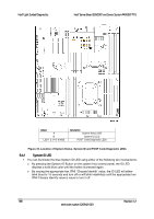
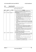
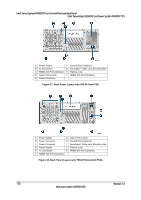
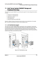
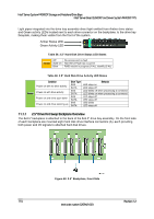
Intel® Server Board S2600CP and Server System P4000CP TPS Intel® Server System P4000CP Front Control Panel and Back Panel 10. Intel® Server System P4000CP Front Control Panel and Back Panel Intel® Server System P4000CP family include a Front Control Panel on the front of the system providing push button system controls, LED indicators for several system features and additional system I/O features. The front panel is identical across different options of Intel® Server System P4000CP family. Intel® Server System P4000CP family provide two different back panel, supporting 550-W fixed power supply and 750-W redundant power supply. This section describes the features and functions of the front panel and back panel. 10.1 Front Control Panel Overview This Front Control Panel conforms to SSI specification with one exception that up to 4 LAN act/link LEDs are supported. The common front panel can support either the standard SSI 2x12 cable interconnect (2 LAN ports) or an Intel customized 2x15 cable interconnect (4 LAN ports). The Front Control Panel has the following features: Power button with integrated power LED (green) System ID with integrated ID LED (blue) System Status LED (green/amber) System Reset button HDD activity LED 4 NIC activity/link LEDs NMI button Two USB ports 10.1.1 Front Control Panel LED/Button Functionality The following figure shows the layout of Front Control Panel: Figure 36. Front Control Panel LED/Button Arragement Revision 1.2 109 Intel order number G26942-003
-
 1
1 -
2
-
3
-
4
-
5
-
6
-
7
-
8
-
9
-
10
-
11
-
12
-
13
-
14
-
15
-
16
-
17
-
18
-
19
-
20
-
21
-
22
-
23
-
24
-
25
-
26
-
27
-
28
-
29
-
30
-
31
-
32
-
33
-
34
-
35
-
36
-
37
-
38
-
39
-
40
-
41
-
42
-
43
-
44
-
45
-
46
-
47
-
48
-
49
-
50
-
51
-
52
-
53
-
54
-
55
-
56
-
57
-
58
-
59
-
60
-
61
-
62
-
63
-
64
-
65
-
66
-
67
-
68
-
69
-
70
-
71
-
72
-
73
-
74
-
75
-
76
-
77
-
78
-
79
-
80
-
81
-
82
-
83
-
84
-
85
-
86
-
87
-
88
-
89
-
90
-
91
-
92
-
93
-
94
-
95
-
96
-
97
-
98
-
99
-
100
-
101
-
102
-
103
-
104
-
105
-
106
-
107
-
108
-
109
-
110
-
111
-
112
-
113
-
114
-
115
-
116
-
117
-
118
-
119
-
 120
120 -
 121
121 -
 122
122 -
 123
123 -
 124
124 -
 125
125 -
 126
126 -
 127
127 -
 128
128 -
 129
129 -
 130
130 -
131
-
132
-
133
-
134
-
135
-
136
-
137
-
138
-
139
-
140
-
141
-
142
-
143
-
144
-
145
-
146
-
147
-
148
-
149
-
150
-
151
-
152
-
153
-
154
-
155
-
156
-
157
-
158
-
159
-
160
-
161
-
162
-
163
-
164
-
165
-
166
-
167
-
168
-
169
-
170
-
171
-
172
-
173
-
174
-
175
-
176
-
177
-
178
-
179
-
180
-
181
-
182
-
183
-
184
-
185
-
186
-
187
-
188
-
189
-
190
-
191
-
192
-
193
-
194
-
195
-
196
-
197
-
198
-
199
-
200
-
201
-
202
-
203
-
204
-
205
-
206
-
207
-
208
-
209
-
210
-
211
-
212
-
213
-
214
-
215
-
216
-
217
-
218
-
219
-
220
-
221
-
222
-
223
-
224
-
225
-
226
-
227
-
228
 |
 |