Intel S2600CP Technical Product Specification - Page 66
Network Interface
 |
View all Intel S2600CP manuals
Add to My Manuals
Save this manual to your list of manuals |
Page 66 highlights
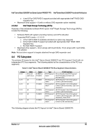
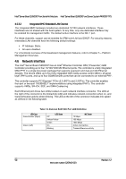
Intel® Server Board S2600CP Functional Architecture Intel® Server Board S2600CP and Server System P4000CP TPS 4.5.3.2 Integrated BMC Embedded LAN Channel The Integrated BMC hardware includes two dedicated 10/100 network interfaces. These interfaces are not shared with the host system. At any time, only one dedicated interface may be enabled for management traffic. The default active interface is the NIC 1 port. For these channels, support can be enabled for IPMI-over-LAN and DHCP. For security reasons, embedded LAN channels have the following default settings: IP Address: Static. All users disabled. For a functional overview of the baseboard management features, refer to Chapter 5 - Platform Management Overview. 4.6 Network Interface The Intel® Server Board S2600CP has an Intel® Ethernet Controller I350 ("Powerville") GbE Controller providing up to four 10/100/1000 Mb Ethernet ports. The controller is a fully integrated MAC/PHY in a single low power package that supports quad-port and dual-port Gb Ethernet designs. The device offers up to four fully integrated GbE media access control (MAC), physical layer (PHY) ports, and up to four SGMII/SerDes ports that can be connected to an external PHY. The controller supports PCI Express* PCIe v2.0 (5GT/s and 2.5GT/s). The controller enables four-port or two-port 1000BASE-T implementations using integrated PHY's. The controller supports VMDq, SR-IOV, EEE, and DMA Coalescing. Each Ethernet port drives two LEDs located on each network interface connector. The LED at the right of the connector is the link/activity LED and indicates network connection when on, and transmit/receive activity when blinking. The LED at the left of the connector indicates link speed as defined in the following table. Table 12. External RJ45 NIC Port LED Definition LED Color Green/Amber (Right) Green (Left) LED State Off Amber/Yellow Green On Blinking 10 Mbps NIC State 100 Mbps 1000 Mbps Active Connection Transmit/Receive activity 50 Revision 1.2 Intel order number G26942-003
-
 1
1 -
2
-
3
-
4
-
5
-
6
-
7
-
8
-
9
-
10
-
11
-
12
-
13
-
14
-
15
-
16
-
17
-
18
-
19
-
20
-
21
-
22
-
23
-
24
-
25
-
26
-
27
-
28
-
29
-
30
-
31
-
32
-
33
-
34
-
35
-
36
-
37
-
38
-
39
-
40
-
41
-
42
-
43
-
44
-
45
-
46
-
47
-
48
-
49
-
50
-
51
-
52
-
53
-
54
-
55
-
56
-
57
-
58
-
59
-
60
-
 61
61 -
 62
62 -
 63
63 -
 64
64 -
 65
65 -
 66
66 -
 67
67 -
 68
68 -
 69
69 -
 70
70 -
 71
71 -
72
-
73
-
74
-
75
-
76
-
77
-
78
-
79
-
80
-
81
-
82
-
83
-
84
-
85
-
86
-
87
-
88
-
89
-
90
-
91
-
92
-
93
-
94
-
95
-
96
-
97
-
98
-
99
-
100
-
101
-
102
-
103
-
104
-
105
-
106
-
107
-
108
-
109
-
110
-
111
-
112
-
113
-
114
-
115
-
116
-
117
-
118
-
119
-
120
-
121
-
122
-
123
-
124
-
125
-
126
-
127
-
128
-
129
-
130
-
131
-
132
-
133
-
134
-
135
-
136
-
137
-
138
-
139
-
140
-
141
-
142
-
143
-
144
-
145
-
146
-
147
-
148
-
149
-
150
-
151
-
152
-
153
-
154
-
155
-
156
-
157
-
158
-
159
-
160
-
161
-
162
-
163
-
164
-
165
-
166
-
167
-
168
-
169
-
170
-
171
-
172
-
173
-
174
-
175
-
176
-
177
-
178
-
179
-
180
-
181
-
182
-
183
-
184
-
185
-
186
-
187
-
188
-
189
-
190
-
191
-
192
-
193
-
194
-
195
-
196
-
197
-
198
-
199
-
200
-
201
-
202
-
203
-
204
-
205
-
206
-
207
-
208
-
209
-
210
-
211
-
212
-
213
-
214
-
215
-
216
-
217
-
218
-
219
-
220
-
221
-
222
-
223
-
224
-
225
-
226
-
227
-
228
 |
 |