Intel S2600CP Technical Product Specification - Page 83
BMC System Management Health Monitoring, IPMI Sensor Characteristics, Processor Sensors, Thermal - fan noise
 |
View all Intel S2600CP manuals
Add to My Manuals
Save this manual to your list of manuals |
Page 83 highlights
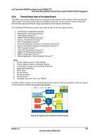
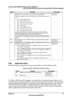
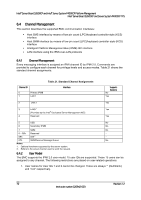
Intel® Server Board S2600CP and Server System P4000CP TPS Intel® Server Board S2600CP and Intel® Server System P4000CP Platform Management 6.3.3 BMC System Management Health Monitoring The BMC tracks the health of each of its IPMI sensors and report failures by providing a "BMC FW Health" sensor of the IPMI 2.0 sensor type Management Subsystem Health with support for the Sensor Failure offset. Only assertions should be logged into the SEL for the Sensor Failure offset. The sensor number of the failed sensor is provided in event data byte 2, as per the IPMI 2.0 Specification. The BMC Firmware Health sensor asserts for any sensor when 10 consecutive sensor errors are read. These are not standard sensor events (that is, threshold crossings or discrete assertions). These are BMC Hardware Access Layer (HAL) errors like I2C NAKs or internal errors while attempting to read a register. If a successful sensor read is completed, the counter resets to zero. IPMI Sensor Characteristics a. Event reading type code: 6Fh (Sensor specific) b. Sensor type code: 28h (Management Subsystem Health) c. Rearm type: Auto If this sensor is implemented, then the following sensor-specific offsets are supported. Table 17. Supported BMC FW Health Sensor Offsets Offset Description 04h Sensor failure Event Logging Assertion and deassertion 6.3.4 Processor Sensors The BMC provides IPMI sensors for processors and associated components, such as voltage regulators and fans. The sensors are implemented on a per-processor basis. Table 18. Processor Sensors Sensor Name Processor Status Digital Thermal Sensor Processor VRD Over-Temperature Indication Processor Voltage Processor Thermal Control (Prochot) Per-Processor Socket Yes Yes Yes Yes Yes Description Processor presence and fault state Relative temperature reading by means of PECI Discrete sensor that indicates a processor VRD has crossed an upper operating temperature threshold Threshold sensor that indicates a processor power-good state Percentage of time a processor is throttling due to thermal conditions 6.3.5 Thermal and Acoustic Management This feature refers to enhanced fan management to keep the system optimally cooled while reducing the amount of noise generated by the system fans. Aggressive acoustics standards might require a trade-off between fan speed and system performance parameters that contribute to the cooling requirements, primarily memory bandwidth. The BIOS, BMC, and SDRs work together to provide control over how this trade-off is determined. This capability requires the BMC to access temperature sensors on the individual memory DIMMs. Additionally, closed-loop thermal throttling is only supported with buffered DIMMs. Revision 1.2 67 Intel order number G26942-003
-
 1
1 -
2
-
3
-
4
-
5
-
6
-
7
-
8
-
9
-
10
-
11
-
12
-
13
-
14
-
15
-
16
-
17
-
18
-
19
-
20
-
21
-
22
-
23
-
24
-
25
-
26
-
27
-
28
-
29
-
30
-
31
-
32
-
33
-
34
-
35
-
36
-
37
-
38
-
39
-
40
-
41
-
42
-
43
-
44
-
45
-
46
-
47
-
48
-
49
-
50
-
51
-
52
-
53
-
54
-
55
-
56
-
57
-
58
-
59
-
60
-
61
-
62
-
63
-
64
-
65
-
66
-
67
-
68
-
69
-
70
-
71
-
72
-
73
-
74
-
75
-
76
-
77
-
 78
78 -
 79
79 -
 80
80 -
 81
81 -
 82
82 -
 83
83 -
 84
84 -
 85
85 -
 86
86 -
 87
87 -
 88
88 -
89
-
90
-
91
-
92
-
93
-
94
-
95
-
96
-
97
-
98
-
99
-
100
-
101
-
102
-
103
-
104
-
105
-
106
-
107
-
108
-
109
-
110
-
111
-
112
-
113
-
114
-
115
-
116
-
117
-
118
-
119
-
120
-
121
-
122
-
123
-
124
-
125
-
126
-
127
-
128
-
129
-
130
-
131
-
132
-
133
-
134
-
135
-
136
-
137
-
138
-
139
-
140
-
141
-
142
-
143
-
144
-
145
-
146
-
147
-
148
-
149
-
150
-
151
-
152
-
153
-
154
-
155
-
156
-
157
-
158
-
159
-
160
-
161
-
162
-
163
-
164
-
165
-
166
-
167
-
168
-
169
-
170
-
171
-
172
-
173
-
174
-
175
-
176
-
177
-
178
-
179
-
180
-
181
-
182
-
183
-
184
-
185
-
186
-
187
-
188
-
189
-
190
-
191
-
192
-
193
-
194
-
195
-
196
-
197
-
198
-
199
-
200
-
201
-
202
-
203
-
204
-
205
-
206
-
207
-
208
-
209
-
210
-
211
-
212
-
213
-
214
-
215
-
216
-
217
-
218
-
219
-
220
-
221
-
222
-
223
-
224
-
225
-
226
-
227
-
228
 |
 |