Intel S2600CP Technical Product Specification - Page 179
Table 132. Ripple and Noise, Differential Noise test setup, Table 133. Output Voltage
 |
View all Intel S2600CP manuals
Add to My Manuals
Save this manual to your list of manuals |
Page 179 highlights
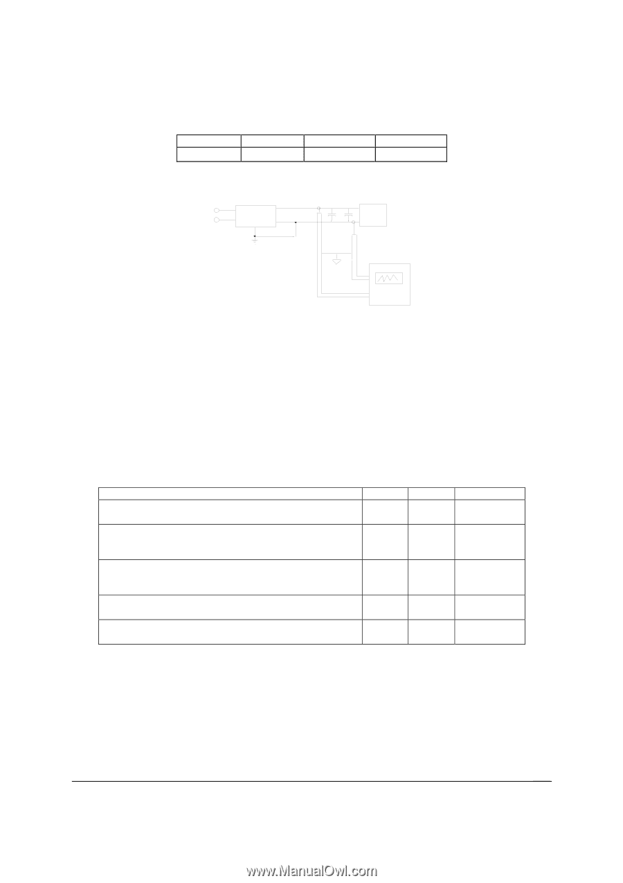
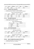
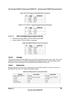
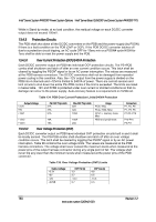
Intel® Server Board S2600CP and Server System P4000CP TPS Intel® Server System P4000CP Power System Options +3.3V 50mVp-p Table 132. Ripple and Noise +5V 50mVp-p -12V 120mVp-p +5VSB 50mVp-p The test set-up shall be as shown below. VOUT AC HOT POWER SUPPLY AC NEUTRAL VRETURN 10uF .1uF LOAD LOAD MUST BE ISOLATED FROM THE GROUND OF THE POWER SUPPLY AC GROUND GENERAL NOTES: 1. LOAD THE OUTPUT WITH ITS MINIMUM LOAD CURRENT. 2. CONNECT THE PROBES AS SHOWN. 3. REPEAT THE MEASUREMENTS WITH THE MAXIMUM LOAD ON THE OUTPUT. SCOPE SCOPE NOTE: USE A TEKTRONIX 7834 OSCILLOSCOPE WITH 7A13 AND DIFFERENTIAL PROBE P6055 OR EQUIVALENT. Note: When performing this test, the probe clips and capacitors should be located close to the load. Figure 63. Differential Noise test setup 13.4.2.15 Timing Requirements Below are timing requirements for the power on/off of the PDB DC/DC converters. The +3.3V, +5V and +12V output voltages should start to rise approximately at the same time. All outputs must rise monotonically. Table 133. Output Voltage Timing Description Output voltage rise time for each main output; 3.3V, 5V, -12V and 5Vstby. The main DC/DC converters (3.3V, 5V, -12V) shall be in regulation limits within this time after the 12V input has reached 11.4V. The main DC/DC converters (3.3V, 5V, -12V) must drop below regulation limits within this time after the 12V input has dropped below 11.4V. The 5Vstby converter shall be in regulation limits within this time after the 12Vstby has reach 11.4V. The 5Vstby converter must power off within this time after the 12Vstby input has dropped below 11.4V. Min 1.0 Max 20 20 20 20 20 Units msec msec msec msec msec 13.4.2.16 Residual Voltage Immunity in Standby Mode Each DC/DC converter is immune to any residual voltage placed on its respective output (typically a leakage voltage through the system from standby output) up to 500mV. This residual voltage does not have any adverse effect on each DC/DC converter, such as: no additional power dissipation or over-stressing/over-heating any internal components or adversely affecting the turn-on performance (no protection circuits tripping during turn on). Revision 1.2 163 Intel order number G26942-003
-
 1
1 -
2
-
3
-
4
-
5
-
6
-
7
-
8
-
9
-
10
-
11
-
12
-
13
-
14
-
15
-
16
-
17
-
18
-
19
-
20
-
21
-
22
-
23
-
24
-
25
-
26
-
27
-
28
-
29
-
30
-
31
-
32
-
33
-
34
-
35
-
36
-
37
-
38
-
39
-
40
-
41
-
42
-
43
-
44
-
45
-
46
-
47
-
48
-
49
-
50
-
51
-
52
-
53
-
54
-
55
-
56
-
57
-
58
-
59
-
60
-
61
-
62
-
63
-
64
-
65
-
66
-
67
-
68
-
69
-
70
-
71
-
72
-
73
-
74
-
75
-
76
-
77
-
78
-
79
-
80
-
81
-
82
-
83
-
84
-
85
-
86
-
87
-
88
-
89
-
90
-
91
-
92
-
93
-
94
-
95
-
96
-
97
-
98
-
99
-
100
-
101
-
102
-
103
-
104
-
105
-
106
-
107
-
108
-
109
-
110
-
111
-
112
-
113
-
114
-
115
-
116
-
117
-
118
-
119
-
120
-
121
-
122
-
123
-
124
-
125
-
126
-
127
-
128
-
129
-
130
-
131
-
132
-
133
-
134
-
135
-
136
-
137
-
138
-
139
-
140
-
141
-
142
-
143
-
144
-
145
-
146
-
147
-
148
-
149
-
150
-
151
-
152
-
153
-
154
-
155
-
156
-
157
-
158
-
159
-
160
-
161
-
162
-
163
-
164
-
165
-
166
-
167
-
168
-
169
-
170
-
171
-
172
-
173
-
 174
174 -
 175
175 -
 176
176 -
 177
177 -
 178
178 -
 179
179 -
 180
180 -
 181
181 -
 182
182 -
 183
183 -
 184
184 -
185
-
186
-
187
-
188
-
189
-
190
-
191
-
192
-
193
-
194
-
195
-
196
-
197
-
198
-
199
-
200
-
201
-
202
-
203
-
204
-
205
-
206
-
207
-
208
-
209
-
210
-
211
-
212
-
213
-
214
-
215
-
216
-
217
-
218
-
219
-
220
-
221
-
222
-
223
-
224
-
225
-
226
-
227
-
228
 |
 |