Intel S2600CP Technical Product Specification - Page 171
DC Output Specification
 |
View all Intel S2600CP manuals
Add to My Manuals
Save this manual to your list of manuals |
Page 171 highlights
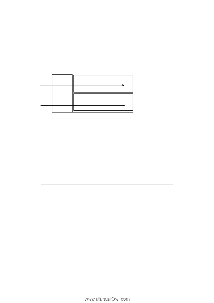
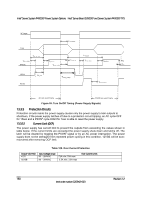
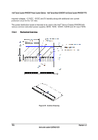
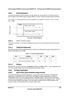
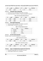
Intel® Server Board S2600CP and Server System P4000CP TPS Intel® Server System P4000CP Power System Options 13.4.1.1 Airflow Requirements The power distribution board shall get enough airflow for cooling DC/DC converters from the fans located in the Power Supply modules. Below is a basic drawing showing airflow direction. The amount of cooling airflow that will be available to the DC/DC converters is to be no less then 1.2M/s. PDB Rear power supply Front power supply Airflow direction Figure 62. Airflow Diagram 13.4.1.2 DC/DC converter cooling The dc/dc converters on the power distribution board are in series airflow path with the power supplies. 13.4.1.3 Temperature Requirements The PDB operates within all specified limits over the Top temperature range. Some amount of airflow shall pass over the PDB. Table 111. Thermal Requirements Item Top Description Operating temperature range. Min 0 Max 50 Units C Tnon-op Non-operating temperature range. -40 70 C 13.4.1.4 Efficiency Each DC/DC converter shall have a minimum efficiency of 85% at 50% ~ 100% loads and over +12V line voltage range and over temperature and humidity range. 13.4.2 DC Output Specification 13.4.2.1 Input Connector (power distribution mating connector) The power distribution provides 2 power pin, a card edge output connection for power and signal that is compatible with a 2x25 Power Card Edge connector (equivalent to 2x25 pin configuration of the FCI power card connector 10035388-102LF). The FCI power card edge connector is a new version of the PCE from FCI used to raise the card edge by 0.031" to allow for future 0.093" PCBs in the system. The card edge connector has no keying features; the keying method is accomplished by the system sheet metal. Revision 1.2 155 Intel order number G26942-003
-
 1
1 -
2
-
3
-
4
-
5
-
6
-
7
-
8
-
9
-
10
-
11
-
12
-
13
-
14
-
15
-
16
-
17
-
18
-
19
-
20
-
21
-
22
-
23
-
24
-
25
-
26
-
27
-
28
-
29
-
30
-
31
-
32
-
33
-
34
-
35
-
36
-
37
-
38
-
39
-
40
-
41
-
42
-
43
-
44
-
45
-
46
-
47
-
48
-
49
-
50
-
51
-
52
-
53
-
54
-
55
-
56
-
57
-
58
-
59
-
60
-
61
-
62
-
63
-
64
-
65
-
66
-
67
-
68
-
69
-
70
-
71
-
72
-
73
-
74
-
75
-
76
-
77
-
78
-
79
-
80
-
81
-
82
-
83
-
84
-
85
-
86
-
87
-
88
-
89
-
90
-
91
-
92
-
93
-
94
-
95
-
96
-
97
-
98
-
99
-
100
-
101
-
102
-
103
-
104
-
105
-
106
-
107
-
108
-
109
-
110
-
111
-
112
-
113
-
114
-
115
-
116
-
117
-
118
-
119
-
120
-
121
-
122
-
123
-
124
-
125
-
126
-
127
-
128
-
129
-
130
-
131
-
132
-
133
-
134
-
135
-
136
-
137
-
138
-
139
-
140
-
141
-
142
-
143
-
144
-
145
-
146
-
147
-
148
-
149
-
150
-
151
-
152
-
153
-
154
-
155
-
156
-
157
-
158
-
159
-
160
-
161
-
162
-
163
-
164
-
165
-
 166
166 -
 167
167 -
 168
168 -
 169
169 -
 170
170 -
 171
171 -
 172
172 -
 173
173 -
 174
174 -
 175
175 -
 176
176 -
177
-
178
-
179
-
180
-
181
-
182
-
183
-
184
-
185
-
186
-
187
-
188
-
189
-
190
-
191
-
192
-
193
-
194
-
195
-
196
-
197
-
198
-
199
-
200
-
201
-
202
-
203
-
204
-
205
-
206
-
207
-
208
-
209
-
210
-
211
-
212
-
213
-
214
-
215
-
216
-
217
-
218
-
219
-
220
-
221
-
222
-
223
-
224
-
225
-
226
-
227
-
228
 |
 |