Intel S2600CP Technical Product Specification - Page 84
Advanced, System Acoustic and Performance, Configuration
 |
View all Intel S2600CP manuals
Add to My Manuals
Save this manual to your list of manuals |
Page 84 highlights
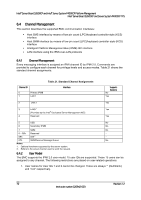
Intel® Server Board S2600CP and Intel® Server System P4000CP Platform Management Intel® Server Board S2600CP and Server System P4000CP TPS The server board offers multiple thermal and acoustic management features to maintain comprehensive thermal protection as well as intelligent fan speed control. The features can be adjusted in BIOS interface with path BIOS > Advanced > System Acoustic and Performance Configuration. 6.3.5.1 Set Throttling Mode Select the most appropriate memory thermal throttling mechanism for memory sub-system from [Auto], [DCLTT], [SCLTT] and [SOLTT]. [Auto] - BIOS automatically detect and identify the appropriate thermal throttling mechanism based on DIMM type, airflow input, and DIMM sensor availability. [DCLTT] - Dynamic Closed Loop Thermal Throttling: for the SOD DIMM with system airflow input [SCLTT] - Static Close Loop Thermal Throttling: for the SOD DIMM without system airflow input [SOLTT] - Static Open Loop Thermal Throttling: for the DIMMs without sensor on dimm (SOD) The default setting is [Auto]. 6.3.5.2 Altitude Select the proper altitude that the system is distributed from [300m or less], [301m-900m], [901m-1500m], [Above 1500m] options. Lower altitude selection can lead to potential thermal risk. And higher altitude selection provides better cooling but with undesired acoustic and fan power consumption. If the altitude is known, higher altitude is recommended in order to provide sufficient cooling. The default setting is [301m - 900m]. 6.3.5.3 Set Fan Profile [Performance] and [Acoustic] fan profiles are available to select. The Acoustic mode offers best acoustic experience and appropriate cooling capability covering mainstream and majority of the add-in cards. Performance mode is designed to provide sufficient cooling capability covering all kinds of add-in cards on the market. The default setting is [Performance] 6.3.5.4 Fan PWM Offset This feature is reserved for manual adjustment to the minimum fan speed curves. The valid range is from [0 to 100] which stands for 0% to 100% PWM adding to the minimum fan speed. This feature is valid when Quiet Fan Idle Mode is at Enabled state. The default setting is [0] 6.3.5.5 Quiet Fan Idle Mode This feature can be [Enabled] or [Disabled]. If enabled, the fan will either stopped or shift to a lower speed when the aggregate sensor temperatures are satisfied indicating the system is at ideal thermal/light loading conditions. When the aggregate sensor temperatures not satisfied, the fan will shift back to normal control curves. If disabled, the fan will never stopped or shift into lower fan speed whatever the aggregate sensor temperatures are satisfied or not. The default setting is [Disabled] Note: 1. The above features may or may not be in effective depends on the actual thermal characters of a specific system. 2. Refer to Fan Control Whitepaper for the board in third party chassis fan speed control customization. 68 Revision 1.2 Intel order number G26942-003
-
 1
1 -
2
-
3
-
4
-
5
-
6
-
7
-
8
-
9
-
10
-
11
-
12
-
13
-
14
-
15
-
16
-
17
-
18
-
19
-
20
-
21
-
22
-
23
-
24
-
25
-
26
-
27
-
28
-
29
-
30
-
31
-
32
-
33
-
34
-
35
-
36
-
37
-
38
-
39
-
40
-
41
-
42
-
43
-
44
-
45
-
46
-
47
-
48
-
49
-
50
-
51
-
52
-
53
-
54
-
55
-
56
-
57
-
58
-
59
-
60
-
61
-
62
-
63
-
64
-
65
-
66
-
67
-
68
-
69
-
70
-
71
-
72
-
73
-
74
-
75
-
76
-
77
-
78
-
 79
79 -
 80
80 -
 81
81 -
 82
82 -
 83
83 -
 84
84 -
 85
85 -
 86
86 -
 87
87 -
 88
88 -
 89
89 -
90
-
91
-
92
-
93
-
94
-
95
-
96
-
97
-
98
-
99
-
100
-
101
-
102
-
103
-
104
-
105
-
106
-
107
-
108
-
109
-
110
-
111
-
112
-
113
-
114
-
115
-
116
-
117
-
118
-
119
-
120
-
121
-
122
-
123
-
124
-
125
-
126
-
127
-
128
-
129
-
130
-
131
-
132
-
133
-
134
-
135
-
136
-
137
-
138
-
139
-
140
-
141
-
142
-
143
-
144
-
145
-
146
-
147
-
148
-
149
-
150
-
151
-
152
-
153
-
154
-
155
-
156
-
157
-
158
-
159
-
160
-
161
-
162
-
163
-
164
-
165
-
166
-
167
-
168
-
169
-
170
-
171
-
172
-
173
-
174
-
175
-
176
-
177
-
178
-
179
-
180
-
181
-
182
-
183
-
184
-
185
-
186
-
187
-
188
-
189
-
190
-
191
-
192
-
193
-
194
-
195
-
196
-
197
-
198
-
199
-
200
-
201
-
202
-
203
-
204
-
205
-
206
-
207
-
208
-
209
-
210
-
211
-
212
-
213
-
214
-
215
-
216
-
217
-
218
-
219
-
220
-
221
-
222
-
223
-
224
-
225
-
226
-
227
-
228
 |
 |