Intel S2600CP Technical Product Specification - Page 82
Assertion/Deassertion, Readable Value/Offsets, Event Data, Rearm Sensors, Default Hysteresis, - manual
 |
View all Intel S2600CP manuals
Add to My Manuals
Save this manual to your list of manuals |
Page 82 highlights
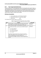
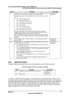
Intel® Server Board S2600CP and Intel® Server System P4000CP Platform Management Intel® Server Board S2600CP and Server System P4000CP TPS - [u,l][nr,c,nc] upper non-recoverable, upper critical, upper non-critical, lower nonrecoverable, lower critical, lower non-critical uc, lc upper critical, lower critical Event triggers are supported event-generating offsets for discrete type sensors. The offsets can be found in the Generic Event/Reading Type Code or Sensor Type Code tables in the Intelligent Platform Management Interface Specification Second Generation Version 2.0, depending on whether the sensor event/reading type is generic or a sensorspecific response. 4. Assertion/Deassertion Assertion and de-assertion indicators reveal the type of events this sensor generates: - As: Assertion - De: De-assertion 5. Readable Value/Offsets - Readable value indicates the type of value returned for threshold and other nondiscrete type sensors. - Readable offsets indicate the offsets for discrete sensors that are readable by means of the Get Sensor Reading command. Unless otherwise indicated, event triggers are readable. Readable offsets consist of the reading type offsets that do not generate events. 6. Event Data Event data is the data that is included in an event message generated by the associated sensor. For threshold-based sensors, these abbreviations are used: - R: Reading value - T: Threshold value 7. Rearm Sensors The rearm is a request for the event status for a sensor to be rechecked and updated upon a transition between good and bad states. Rearming the sensors can be done manually or automatically. This column indicates the type supported by the sensor. The following abbreviations are used in the comment column to describe a sensor: - A: Auto-rearm - M: Manual rearm - I: Rearm by init agent 8. Default Hysteresis The hysteresis setting applies to all thresholds of the sensor. This column provides the count of hysteresis for the sensor, which can be 1 or 2 (positive or negative hysteresis). 9. Criticality Criticality is a classification of the severity and nature of the condition. It also controls the behavior of the front panel status LED. 10. Standby Some sensors operate on standby power. These sensors may be accessed and/or generate events when the main (system) power is off, but AC power is present. 66 Revision 1.2 Intel order number G26942-003
-
 1
1 -
2
-
3
-
4
-
5
-
6
-
7
-
8
-
9
-
10
-
11
-
12
-
13
-
14
-
15
-
16
-
17
-
18
-
19
-
20
-
21
-
22
-
23
-
24
-
25
-
26
-
27
-
28
-
29
-
30
-
31
-
32
-
33
-
34
-
35
-
36
-
37
-
38
-
39
-
40
-
41
-
42
-
43
-
44
-
45
-
46
-
47
-
48
-
49
-
50
-
51
-
52
-
53
-
54
-
55
-
56
-
57
-
58
-
59
-
60
-
61
-
62
-
63
-
64
-
65
-
66
-
67
-
68
-
69
-
70
-
71
-
72
-
73
-
74
-
75
-
76
-
 77
77 -
 78
78 -
 79
79 -
 80
80 -
 81
81 -
 82
82 -
 83
83 -
 84
84 -
 85
85 -
 86
86 -
 87
87 -
88
-
89
-
90
-
91
-
92
-
93
-
94
-
95
-
96
-
97
-
98
-
99
-
100
-
101
-
102
-
103
-
104
-
105
-
106
-
107
-
108
-
109
-
110
-
111
-
112
-
113
-
114
-
115
-
116
-
117
-
118
-
119
-
120
-
121
-
122
-
123
-
124
-
125
-
126
-
127
-
128
-
129
-
130
-
131
-
132
-
133
-
134
-
135
-
136
-
137
-
138
-
139
-
140
-
141
-
142
-
143
-
144
-
145
-
146
-
147
-
148
-
149
-
150
-
151
-
152
-
153
-
154
-
155
-
156
-
157
-
158
-
159
-
160
-
161
-
162
-
163
-
164
-
165
-
166
-
167
-
168
-
169
-
170
-
171
-
172
-
173
-
174
-
175
-
176
-
177
-
178
-
179
-
180
-
181
-
182
-
183
-
184
-
185
-
186
-
187
-
188
-
189
-
190
-
191
-
192
-
193
-
194
-
195
-
196
-
197
-
198
-
199
-
200
-
201
-
202
-
203
-
204
-
205
-
206
-
207
-
208
-
209
-
210
-
211
-
212
-
213
-
214
-
215
-
216
-
217
-
218
-
219
-
220
-
221
-
222
-
223
-
224
-
225
-
226
-
227
-
228
 |
 |
