Intel S2600CP Technical Product Specification - Page 127
Back Panel Overview
 |
View all Intel S2600CP manuals
Add to My Manuals
Save this manual to your list of manuals |
Page 127 highlights
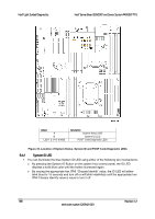
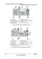
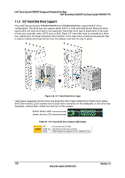
Intel® Server Board S2600CP and Server System P4000CP TPS Intel® Server System P4000CP Front Control Panel and Back Panel 10.1.2 Front Control Panel LED Status The following table provides a description of each LED status. Table 58. Front Control Panel LED Status LED Power/Sleep Status Color Green Green Green Green Amber Amber Global HDD Activity LAN 1-4 Activity/Link Chassis Identification Green Green Green Blue Blue Condition On Blink Off On Blink On Blink Off Blink Off On Blink Off On Blink Off What It Means Power on or S0 sleep. S1 sleep or S3 standby only for workstation baseboards. Off (also sleep S4/S5 modes). System ready/No alarm. System ready, but degraded: redundancy lost such as PS or fan failure; non-critical temp/voltage threshold; battery failure; or predictive PS failure. Critical alarm: Voltage, thermal, or power fault; CPU missing; insufficient power unit redundancy resource offset asserted. Non-Critical failure: Critical temp/voltage threshold; VDR hot asserted; min number fans not present or failed. AC power off: System unplugged. AC power on: System powered off and in standby, no prior degraded/non-critical/critical state. HDD access. No access and no fault. LAN link LAN access. Idle. Front panel chassis ID button pressed. Unit selected for identification by software. No identification. 10.2 Back Panel Overview The following figure shows the layout of Back Panel with 550-W fixed power supply and 750-W redundant power supplies. Revision 1.2 111 Intel order number G26942-003
-
 1
1 -
2
-
3
-
4
-
5
-
6
-
7
-
8
-
9
-
10
-
11
-
12
-
13
-
14
-
15
-
16
-
17
-
18
-
19
-
20
-
21
-
22
-
23
-
24
-
25
-
26
-
27
-
28
-
29
-
30
-
31
-
32
-
33
-
34
-
35
-
36
-
37
-
38
-
39
-
40
-
41
-
42
-
43
-
44
-
45
-
46
-
47
-
48
-
49
-
50
-
51
-
52
-
53
-
54
-
55
-
56
-
57
-
58
-
59
-
60
-
61
-
62
-
63
-
64
-
65
-
66
-
67
-
68
-
69
-
70
-
71
-
72
-
73
-
74
-
75
-
76
-
77
-
78
-
79
-
80
-
81
-
82
-
83
-
84
-
85
-
86
-
87
-
88
-
89
-
90
-
91
-
92
-
93
-
94
-
95
-
96
-
97
-
98
-
99
-
100
-
101
-
102
-
103
-
104
-
105
-
106
-
107
-
108
-
109
-
110
-
111
-
112
-
113
-
114
-
115
-
116
-
117
-
118
-
119
-
120
-
121
-
 122
122 -
 123
123 -
 124
124 -
 125
125 -
 126
126 -
 127
127 -
 128
128 -
 129
129 -
 130
130 -
 131
131 -
 132
132 -
133
-
134
-
135
-
136
-
137
-
138
-
139
-
140
-
141
-
142
-
143
-
144
-
145
-
146
-
147
-
148
-
149
-
150
-
151
-
152
-
153
-
154
-
155
-
156
-
157
-
158
-
159
-
160
-
161
-
162
-
163
-
164
-
165
-
166
-
167
-
168
-
169
-
170
-
171
-
172
-
173
-
174
-
175
-
176
-
177
-
178
-
179
-
180
-
181
-
182
-
183
-
184
-
185
-
186
-
187
-
188
-
189
-
190
-
191
-
192
-
193
-
194
-
195
-
196
-
197
-
198
-
199
-
200
-
201
-
202
-
203
-
204
-
205
-
206
-
207
-
208
-
209
-
210
-
211
-
212
-
213
-
214
-
215
-
216
-
217
-
218
-
219
-
220
-
221
-
222
-
223
-
224
-
225
-
226
-
227
-
228
 |
 |
