Intel S2600CP Technical Product Specification - Page 208
Sensor Type
 |
View all Intel S2600CP manuals
Add to My Manuals
Save this manual to your list of manuals |
Page 208 highlights
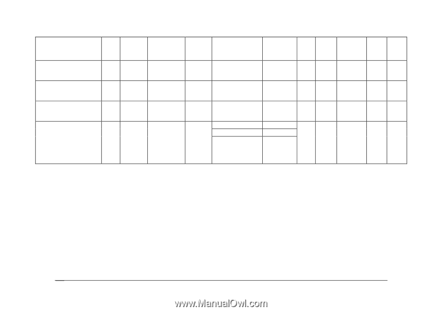
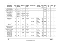
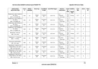
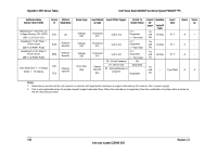
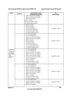
Appendix C: BMC Sensor Tables Intel® Server Board S2600CP and Server System P4000CP TPS Full Sensor Name (Sensor name in SDR) Sensor Platform # Applicability Baseboard +1.35V P2 Low Voltage Memory CD VDDQ E7h All (BB +1.35 P2LV CD) Baseboard +3.3V Riser 1 Power Good (BB +3.3 RSR1 PGD) EAh Platform Specific Baseboard +3.3V Riser 2 Power Good (BB +3.3 RSR2 PGD) EBh Platform Specific Hard Disk Drive 1 -15 Status (HDD 1 - 15 Status) F0h - Chassisspecific FEh Sensor Type Voltage 02h Voltage 02h Voltage 02h Drive Slot 0Dh Event/Readi Event Offset Triggers ng Type Contrib. To System Status Threshold 01h Threshold 01h Threshold 01h Sensor Specific 6Fh [u,l] [c,nc] [u,l] [c,nc] [u,l] [c,nc] 00 - Drive Presence 01- Drive Fault 07 - Rebuild/Remap in progress nc = Degraded c = Non-fatal nc = Degraded c = Non-fatal nc = Degraded c = Non-fatal OK Degraded Degraded Assert/ De- assert As and De Readable Value/Of fsets Analog As and Analog De As and Analog De As and - De Event Data R, T R, T R, T Trig Offset Rearm A A A A Standby - - - X Notes: 1. Redundancy sensors will be only present on systems with appropriate hardware to support redundancy (for instance, fan or power supply). 2. This is only applicable when the system doesn't support redundant fans. When fan redundancy is supported, then the contribution to system state is driven by the fan redundancy sensor. 192 Revision 1.2 Intel order number G26942-003
-
 1
1 -
2
-
3
-
4
-
5
-
6
-
7
-
8
-
9
-
10
-
11
-
12
-
13
-
14
-
15
-
16
-
17
-
18
-
19
-
20
-
21
-
22
-
23
-
24
-
25
-
26
-
27
-
28
-
29
-
30
-
31
-
32
-
33
-
34
-
35
-
36
-
37
-
38
-
39
-
40
-
41
-
42
-
43
-
44
-
45
-
46
-
47
-
48
-
49
-
50
-
51
-
52
-
53
-
54
-
55
-
56
-
57
-
58
-
59
-
60
-
61
-
62
-
63
-
64
-
65
-
66
-
67
-
68
-
69
-
70
-
71
-
72
-
73
-
74
-
75
-
76
-
77
-
78
-
79
-
80
-
81
-
82
-
83
-
84
-
85
-
86
-
87
-
88
-
89
-
90
-
91
-
92
-
93
-
94
-
95
-
96
-
97
-
98
-
99
-
100
-
101
-
102
-
103
-
104
-
105
-
106
-
107
-
108
-
109
-
110
-
111
-
112
-
113
-
114
-
115
-
116
-
117
-
118
-
119
-
120
-
121
-
122
-
123
-
124
-
125
-
126
-
127
-
128
-
129
-
130
-
131
-
132
-
133
-
134
-
135
-
136
-
137
-
138
-
139
-
140
-
141
-
142
-
143
-
144
-
145
-
146
-
147
-
148
-
149
-
150
-
151
-
152
-
153
-
154
-
155
-
156
-
157
-
158
-
159
-
160
-
161
-
162
-
163
-
164
-
165
-
166
-
167
-
168
-
169
-
170
-
171
-
172
-
173
-
174
-
175
-
176
-
177
-
178
-
179
-
180
-
181
-
182
-
183
-
184
-
185
-
186
-
187
-
188
-
189
-
190
-
191
-
192
-
193
-
194
-
195
-
196
-
197
-
198
-
199
-
200
-
201
-
202
-
 203
203 -
 204
204 -
 205
205 -
 206
206 -
 207
207 -
 208
208 -
 209
209 -
 210
210 -
 211
211 -
 212
212 -
 213
213 -
214
-
215
-
216
-
217
-
218
-
219
-
220
-
221
-
222
-
223
-
224
-
225
-
226
-
227
-
228
 |
 |