Intel S2600CP Technical Product Specification - Page 146
Intel S2600CP Manual
 |
View all Intel S2600CP manuals
Add to My Manuals
Save this manual to your list of manuals |
Page 146 highlights
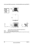
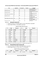
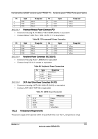
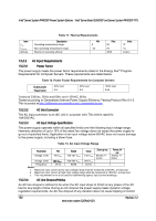
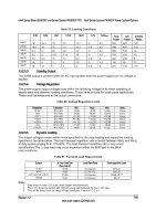
Intel® Server System P4000CP Power System Options Intel® Server Board S2600CP and Server System P4000CP TPS From Length (mm) Extension from P4 100 Extension from P5 100 Power Supply cover exit hole 600 Extension from P7 75 Power Supply cover exit hole 700 Extension from P9 75 To connector # No of pins P5 5 P6 4 P7 4 P8 4 P9 4 P10 4 Description Connector for 5.25" SATA Peripheral Power Connector for 5.25" Peripheral Power Connector for 5.25" 1x4 Legacy HSBP Power Connector 1x4 Legacy HSBP Power Connector 1x4 Legacy HSBP Power/Fixed HDD Adapter Connection 1x4 Legacy HSBP Power/Fixed HDD Adapter Connection 13.2.1.1.1 Main power connector (P1) Connector housing: 24- Pin Molex* Mini-Fit Jr 39-01-2245 (94V2) or equivalent Contact: Molex* Minifit Jr, Crimp 5556 or equivalent Table 66. P1 Main Power Connector Pin 1 2 3 4 5 6 7 8 9 10 11 12 Signal +3.3 VDC +3.3 VDC COM +5 VDC* COM +5 VDC COM PWR OK 5VSB +12V2 +12V2 +3.3 VDC 18 awg color Orange Orange Black Red Black Red Black Gray Purple Yellow/Black Yellow/Black Orange Pin 13 14 15 16 17 18 19 20 21 22 23 24 Signal +3.3 VDC -12 VDC COM PSON# COM COM COM Reserved +5 VDC +5 VDC +5 VDC COM 18 awg color Orange Blue Black Green Black Black Black N.C. Red Red Red Black Note: 3.3V remote sense shall be double crimped into pin 13 if needed to meet regulation limits. 13.2.1.1.2 Processor/Memory Power Connector (P2) Connector housing: 8- Pin Molex* 39-01-2085 (94V2) or equivalent Contact: Molex*, Mini-Fit Jr, HCS, 44476-1111 or equivalent Table 67. P2 Processor#1 Power Connector Pin 1 Signal COM 18 awg color Black Pin 5 Signal +12V1 18 awg color Yellow 130 Revision 1.2 Intel order number G26942-003
-
 1
1 -
2
-
3
-
4
-
5
-
6
-
7
-
8
-
9
-
10
-
11
-
12
-
13
-
14
-
15
-
16
-
17
-
18
-
19
-
20
-
21
-
22
-
23
-
24
-
25
-
26
-
27
-
28
-
29
-
30
-
31
-
32
-
33
-
34
-
35
-
36
-
37
-
38
-
39
-
40
-
41
-
42
-
43
-
44
-
45
-
46
-
47
-
48
-
49
-
50
-
51
-
52
-
53
-
54
-
55
-
56
-
57
-
58
-
59
-
60
-
61
-
62
-
63
-
64
-
65
-
66
-
67
-
68
-
69
-
70
-
71
-
72
-
73
-
74
-
75
-
76
-
77
-
78
-
79
-
80
-
81
-
82
-
83
-
84
-
85
-
86
-
87
-
88
-
89
-
90
-
91
-
92
-
93
-
94
-
95
-
96
-
97
-
98
-
99
-
100
-
101
-
102
-
103
-
104
-
105
-
106
-
107
-
108
-
109
-
110
-
111
-
112
-
113
-
114
-
115
-
116
-
117
-
118
-
119
-
120
-
121
-
122
-
123
-
124
-
125
-
126
-
127
-
128
-
129
-
130
-
131
-
132
-
133
-
134
-
135
-
136
-
137
-
138
-
139
-
140
-
 141
141 -
 142
142 -
 143
143 -
 144
144 -
 145
145 -
 146
146 -
 147
147 -
 148
148 -
 149
149 -
 150
150 -
 151
151 -
152
-
153
-
154
-
155
-
156
-
157
-
158
-
159
-
160
-
161
-
162
-
163
-
164
-
165
-
166
-
167
-
168
-
169
-
170
-
171
-
172
-
173
-
174
-
175
-
176
-
177
-
178
-
179
-
180
-
181
-
182
-
183
-
184
-
185
-
186
-
187
-
188
-
189
-
190
-
191
-
192
-
193
-
194
-
195
-
196
-
197
-
198
-
199
-
200
-
201
-
202
-
203
-
204
-
205
-
206
-
207
-
208
-
209
-
210
-
211
-
212
-
213
-
214
-
215
-
216
-
217
-
218
-
219
-
220
-
221
-
222
-
223
-
224
-
225
-
226
-
227
-
228
 |
 |